Stent delivery device

a technology of stent and stent body, which is applied in the field of stent delivery devices, can solve the problems of constriction, small stent diameter, and difficulty in implanting the self-expandable stent correctly at the desired portion,

Active Publication Date: 2006-11-16
TERUMO KK
View PDF5 Cites 170 Cited by
  • Summary
  • Abstract
  • Description
  • Claims
  • Application Information

AI Technical Summary

Benefits of technology

[0024] A stent delivery device comprises a distal-side tube having a guide wire lumen; a proximal-side tube whose distal portion is fixed to a proximal portion of said distal-side tube; a cylindrical member which encloses a distal side of said distal-side tube and is slidable toward a proximal end of said distal-side tube; a stent housed in said cylindrical member; and a pulling member which extends inside said proximal-side tube, with one end portion thereof fixed to said cylindrical member and is pulled toward said proximal side of said proximal-side tube to move said cylindrical member toward a proximal side of said stent delivery device, wherein said distal-side tube has a proximal-side opening which is open at said proximal side of said distal-side tube and communicates with said guide wire lumen; and a stent-locking portion which is disposed at said distal side of said distal-side tube and contacts a proximal end of said stent accommodated inside said cylindrical member, thus preventing said stent from moving to said proximal side of said stent delivery device; and said stent is formed approximately cylindrically, accommodated in said cylindrical member, with said stent being compressed in an axial direction thereof, and expands outward and returns to a configuration before said stent is compressed, when said stent is implanted in an organism; and

Problems solved by technology

Therefore there is a possibility that the diameter of the stent becomes smaller due to the pressure of the blood vessel with an elapse of time and that a constriction occurs again.
As compared with the balloon expandable stent, it is difficult to implant the self-expandable stent correctly at the desired portion for the reason described below.
The stent is liable to move forward when it expands owing to loosening of the outer tube inside a body cavity and friction between the stent and the body cavity, between the stent and a catheter or between the stent and a valve of a device called an introducer for introducing the delivery system into a patients body.
Thus a long period of time is required to exchange the systems.
The system of WO96 / 31174 is difficult to have a small diameter because it uses three tubular members.
Thus the system has a low operability and has a possibility that the implanting position of medical appliances are set at an unintended position.
Therefore it is difficult to operate the system with one hand.

Method used


Image

  • Stent delivery device
  • Stent delivery device
  • Stent delivery device

Examples


example

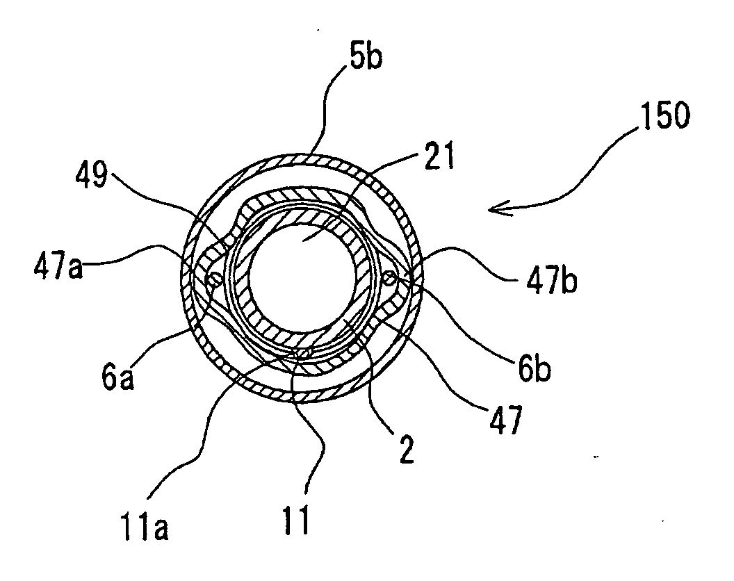
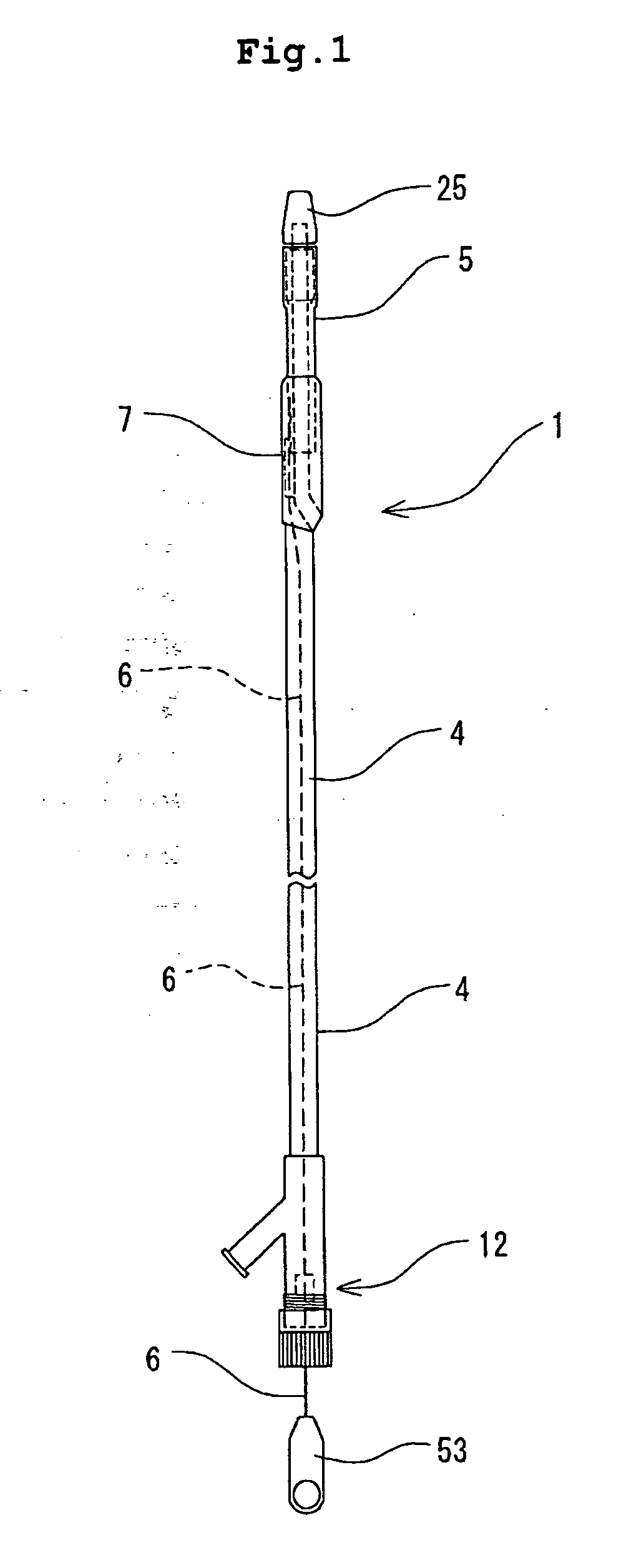
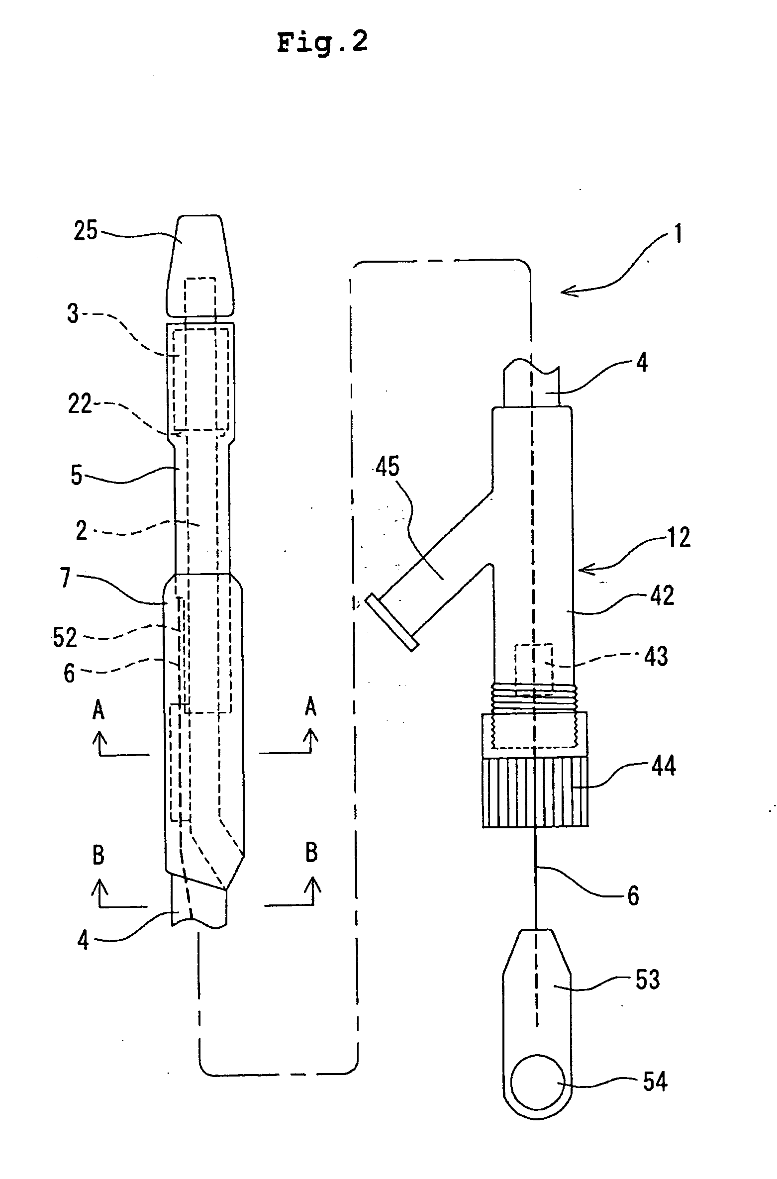
[0177] The stent delivery device shown in FIGS. 1 through 7 was formed. The stent delivery device of this embodiment was formed on condition that a guide wire having a diameter of 0.035 inches. That is, the stent delivery device is of a so-called rapid exchange type. As the distal-side tube, a tube made of polyether ether ketone was used. The outer diameter and inner diameter of the distal-side tube were 1.23 mm and 0.95 mm respectively. As the stent-locking portion, a stainless steel ring was caulked to the outer surface of the distal-side tube. As the distal-end member, a polyester elastomer formed by injection molding was used. The stent was prepared by cutting a piece from a tube made of nickel titanium. As the stent accommodation cylindrical member, a polyimide tube was used. The outer diameter and inner diameter of the stent accommodation cylindrical member were 2.06 mm and 1.8 mm respectively. The outer diameter and inner diameter of the small-diameter portion were 1.60 mm an...


PUM


Abstract

A stent delivery device includes a distal-side tube having a guide wire lumen; a proximal-side tube whose distal portion is fixed to a proximal portion of the distal-side tube; a cylindrical member which encloses a distal side of the distal-side tube and is slidable toward a proximal end of the distal-side tube; a stent accommodated in the cylindrical member; and a pulling member 6 for moving the cylindrical member toward a proximal side of the stent delivery device. The distal-side tube has a proximal-side opening which is open at the proximal side of the distal-side tube; and a stent-locking portion for preventing the stent from moving to the proximal side of the stent delivery device. The outer diameter of the proximal-side tube is set smaller than that of a portion, having a maximum diameter, which is disposed in a region of the stent delivery device which is distal from the proximal-side tube.

Description

BACKGROUND OF THE INVENTION [0001] The present invention relates to a stent delivery device for implanting a stent at a stenosed portion or a closed portion generated in internal organs such as a blood vessel, the bile duct the trachea, the esophagus, the ureter, a digestive tract, and the like. [0002] Stent delivery devices proposed heretofore are used to secure a lumen or a space in a body cavity by implanting the stent at the lumen, the stenosed portion or the closed portion of the body cavity in an internal organ such as the blood vessel, the bile duct, the trachea, the esophagus, the ureter, the digestive tract, and the like. [0003] The stent is classified into a self-expandable stent and a balloon expandable stent in dependence on the function thereof and an implantation method. [0004] The balloon expandable stent which itself has no expanding function. To implant the stent at a desired portion, after the stent is inserted into the desired portion, a balloon disposed in the st...

Claims


Application Information

Patent Timeline
Patent Type & Authority Applications(United States)
IPC IPC(8): A61F2/84A61F2/95A61F2/966
CPCA61F2/966A61F2002/9665A61F2002/9517A61M25/0147A61F2/9517
Inventor MATSUOKA, EMIMORISHITA, KEITAROMORIUCHI, YOUSUKE
Owner TERUMO KK
Why Eureka
Try Eureka