Multi-stage pressure regulator

a pressure regulator and multi-stage technology, applied in fluid pressure control, process and machine control, instruments, etc., can solve the problems of valve b>28/b> oscillation, less flow sensitivity, and not suitable for fuel cell system applications, and achieve the effect of large turn-down ratio

Active Publication Date: 2006-11-23
GM GLOBAL TECH OPERATIONS LLC
View PDF8 Cites 26 Cited by
  • Summary
  • Abstract
  • Description
  • Claims
  • Application Information

AI Technical Summary

Benefits of technology

[0013] In accordance with the teachings of the present invention, a pressure regulator is disclosed that has particular application for an anode input side of a fuel cell system to provide the desired large turn-down ratio. The pressure regulator includes at least two valves positioned in parallel where the first valve is smaller than the second valve. The first valve is opened and closed and the second valve is maintained closed at low flow rates. Once the flow rate is high enough, the first valve is maintained completely open, and the second valve is opened and closed to control the flow at high flow rates.

Problems solved by technology

These types of pressure regulators are not suitable for fuel cell system applications because of the accurate pressure regulation of low flow rates, and the tight flow control necessary for the anode input.
However, this provides less flow sensitivity at low flow rates because as the valve head 30 moves away from the valve seat 36, the size of the orifice 20 would be too large for low flow control, possibly causing the valve 28 to oscillate.

Method used


Image

  • Multi-stage pressure regulator
  • Multi-stage pressure regulator
  • Multi-stage pressure regulator

Examples


Embodiment Construction

[0020] The following discussion of the embodiments of the invention directed to a multi-stage pressure regulator is merely exemplary in nature, and is in no way intended to limit the invention or its applications or uses. Particularly, the multi-stage pressure regulator of the invention has particular application for an anode side of a fuel cell system. However, as will be appreciated by those skilled in the art, the pressure regulator of the invention may have other applications.

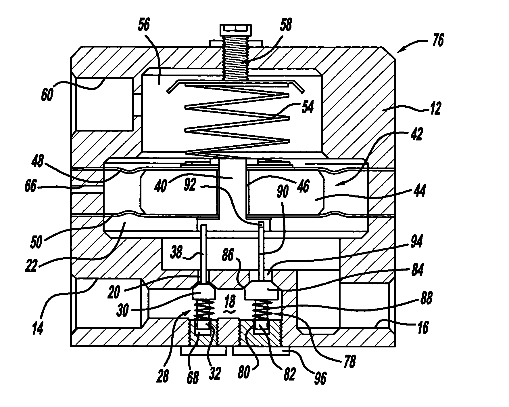
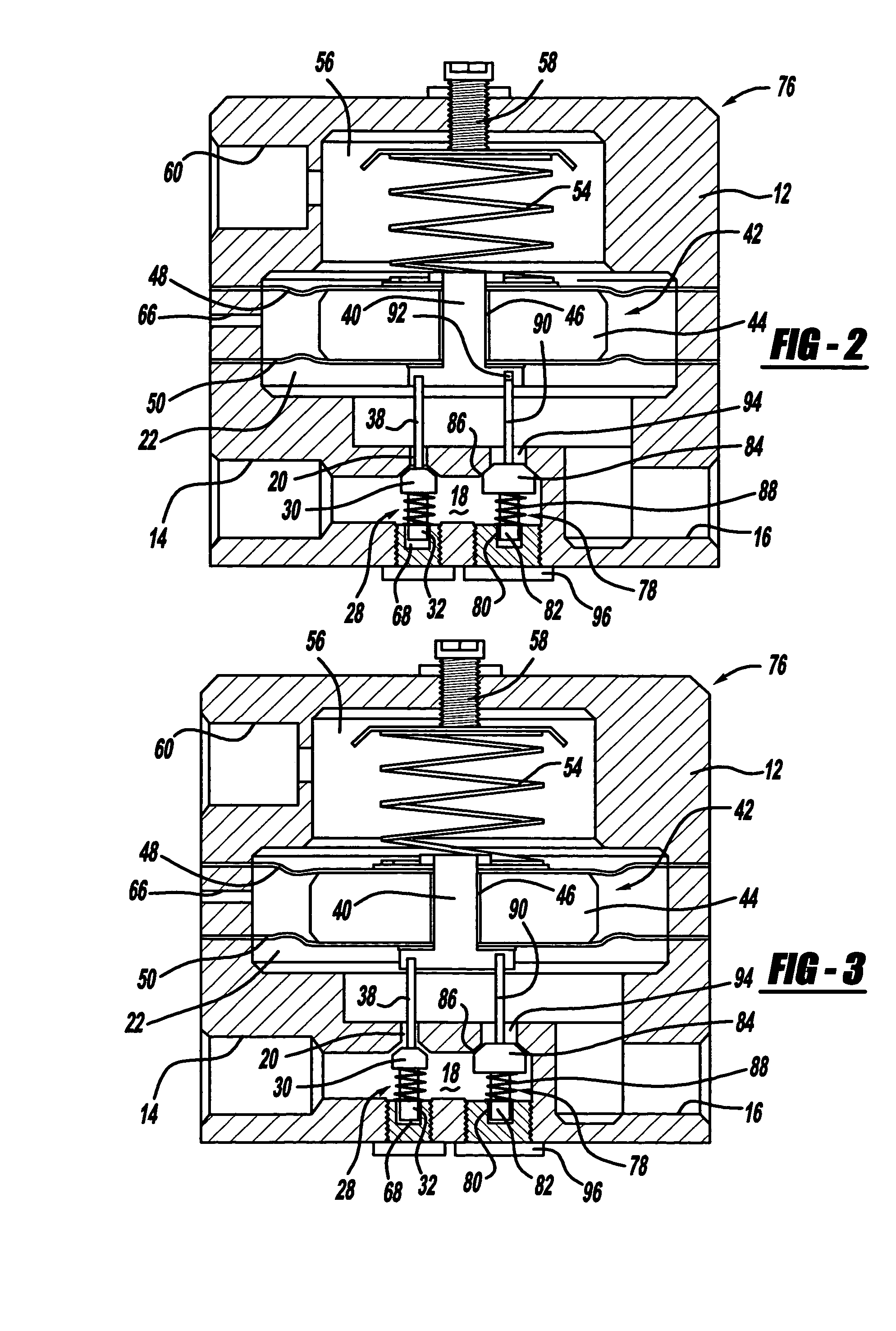
[0021]FIG. 2 is a cross-sectional view of a flow control pressure regulator 76 that has particular application for the anode side of a fuel cell system, as discussed above, according to an embodiment of the present invention, where like elements are identified by the same reference numeral as the pressure regulator 10. The pressure regulator 76 provides greater flow control at low flow rates for a larger turn-down ratio than the pressure regulator 10. In the pressure regulator 76, the valve 28 is sized and...


PUM


Abstract

A pressure regulator that has particular application for an anode input side of a fuel cell system to provide the desired large turn-down ratio. The pressure regulator includes at least two valves positioned in parallel where the first valve is smaller than the second valve. The first valve is opened and closed and the second valve is maintained closed at low flow rates. Once the flow rate is high enough, the first valve is maintained completely open, and the second valve is opened and closed to control the flow at high flow rates.

Description

BACKGROUND OF THE INVENTION [0001] 1. Field of the Invention [0002] This invention relates generally to a pressure regulator and, more particularly, to a pressure regulator that includes multiple valve stages to increase the turn-down ratio of the regulator. [0003] 2. Discussion of the Related Art [0004] Hydrogen is a very attractive fuel because it is clean and can be used to efficiently produce electricity in a fuel cell. The automotive industry expends significant resources in the development of hydrogen fuel cells as a source of power for vehicles. Such vehicles would be more efficient and generate fewer emissions than today's vehicles employing internal combustion engines. [0005] A hydrogen fuel cell is an electrochemical device that includes an anode and a cathode with an electrolyte therebetween. The anode receives hydrogen gas and the cathode receives oxygen or air. The hydrogen gas is dissociated in the anode to generate free protons and electrons. The protons pass through ...

Claims


Application Information

Patent Timeline
Patent Type & Authority Applications(United States)
IPC IPC(8): G05D16/06
CPCG05D16/0672H01M8/04089Y02E60/50H01M8/04753H01M8/04776H01M8/0438G05D16/0663G05D16/0694G05D16/0404Y10T137/7826Y10T137/783Y10T137/8733Y10T137/8741Y10T137/87491
Inventor PECHTOLD, RAINER
Owner GM GLOBAL TECH OPERATIONS LLC
Why Eureka
Try Eureka