High-efficiency enhanced boiler

a boiler and high-efficiency technology, applied in the field of heat exchangers, can solve the problems of large and more expensive devices, and achieve the effects of enhancing convection/conduction couples, enhancing heat transfer relationships, and increasing the surface area involved in heat transfer relationships

Active Publication Date: 2016-12-20
OKONSKI JR JOHN E +1
View PDF30 Cites 1 Cited by
  • Summary
  • Abstract
  • Description
  • Claims
  • Application Information

AI Technical Summary

Benefits of technology

[0009]In devices known in the art, “conventional firetube” and “waste heat recovery” boilers each require many small tubes making successive passes within the boiler. In one embodiment of the invention, however, an enhanced conduit replaces numerous conventional small tubes. In some embodiments, the enhanced conduit incorporates a plurality of fins, each of which extends through a wall of the conduit. In other embodiments, the enhanced conduit incorporates a plurality of tubes along its inner surface, through which a heat transfer medium flows. Both designs enhance the heat transfer relationship between the hot fluid and the heat transfer medium by providing a continuous heat transfer relationship with the heat transfer medium, increasing the surface area involved in the heat transfer relationship and enhancing convection / conduction couples. For some applications, all of the tube banks of other devices in the art can be replaced by one continuous enhanced conduit.
[0010]The High-Efficiency Enhanced Boiler (HEEB) of the present invention offers improvements over conventional designs. A first improvement is a continuous heat transfer relation by surrounding the enhanced conduit with heat transfer medium. A second improvement is the possibility of substantial turndown ratios. A third improvement is the feasibility of manufacturing devices for applications requiring steam pressures in excess of 21.4 atmospheres absolute, whereas conventional firetube boilers have practical limitations. Finally, the HEEB is readily configurable to generate superheated steam.

Problems solved by technology

This can result in larger and more expensive devices.

Method used


Image

  • High-efficiency enhanced boiler
  • High-efficiency enhanced boiler
  • High-efficiency enhanced boiler

Examples


example 1

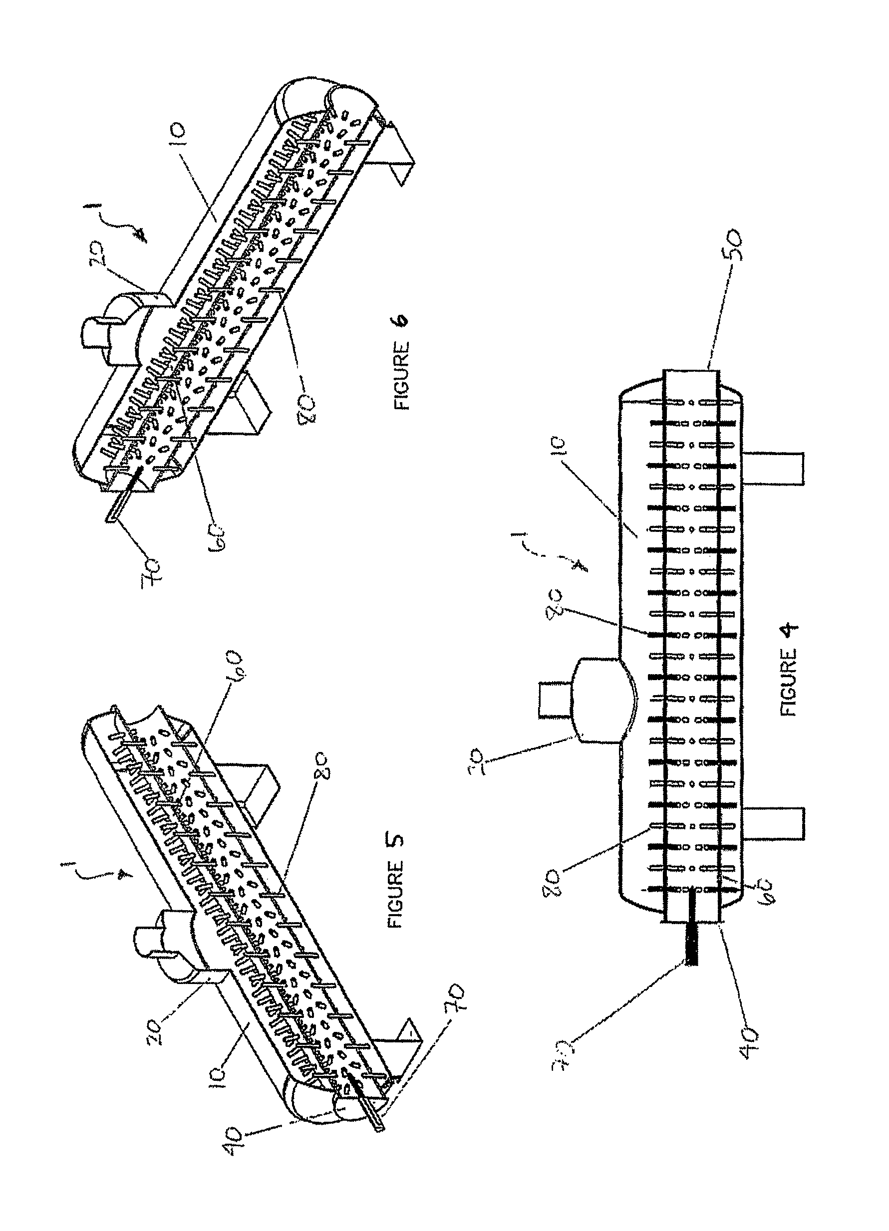
[0059]Referring to FIGS. 7-12, a direct-fired 3-pass 30-horsepower boiler 100 is shown, fabricated in accordance with the present design criteria for a pressure of 10 atmospheres and requiring a one million BTU (British thermal units) natural gas burner. Cylindrical vessel 110 has dimensions of 42-inches O.D. wide by 60-inches O.D. long, with ten-inch diameter enhanced conduit 160 winding through the interior of the vessel. Hot fluid enters boiler 100 through hot fluid inlet 140, passes through enhanced conduit 160, and exits through flue outlet 150. Condensate returns to boiler 100 through feedwater inlet 130. There are 280 ¾″ diameter fins 180 located circumferentially throughout enhanced conduit 160 in sets of ten. Fins 180 are mechanically fastened to enhanced conduit 160 by virtue of a self-locking taper and seal welding. The temperature of the exhausted flue gas is approximately 230 C. The thermal efficiency of such a design is increased, in part, due to the fact that “turn-ar...

example 2

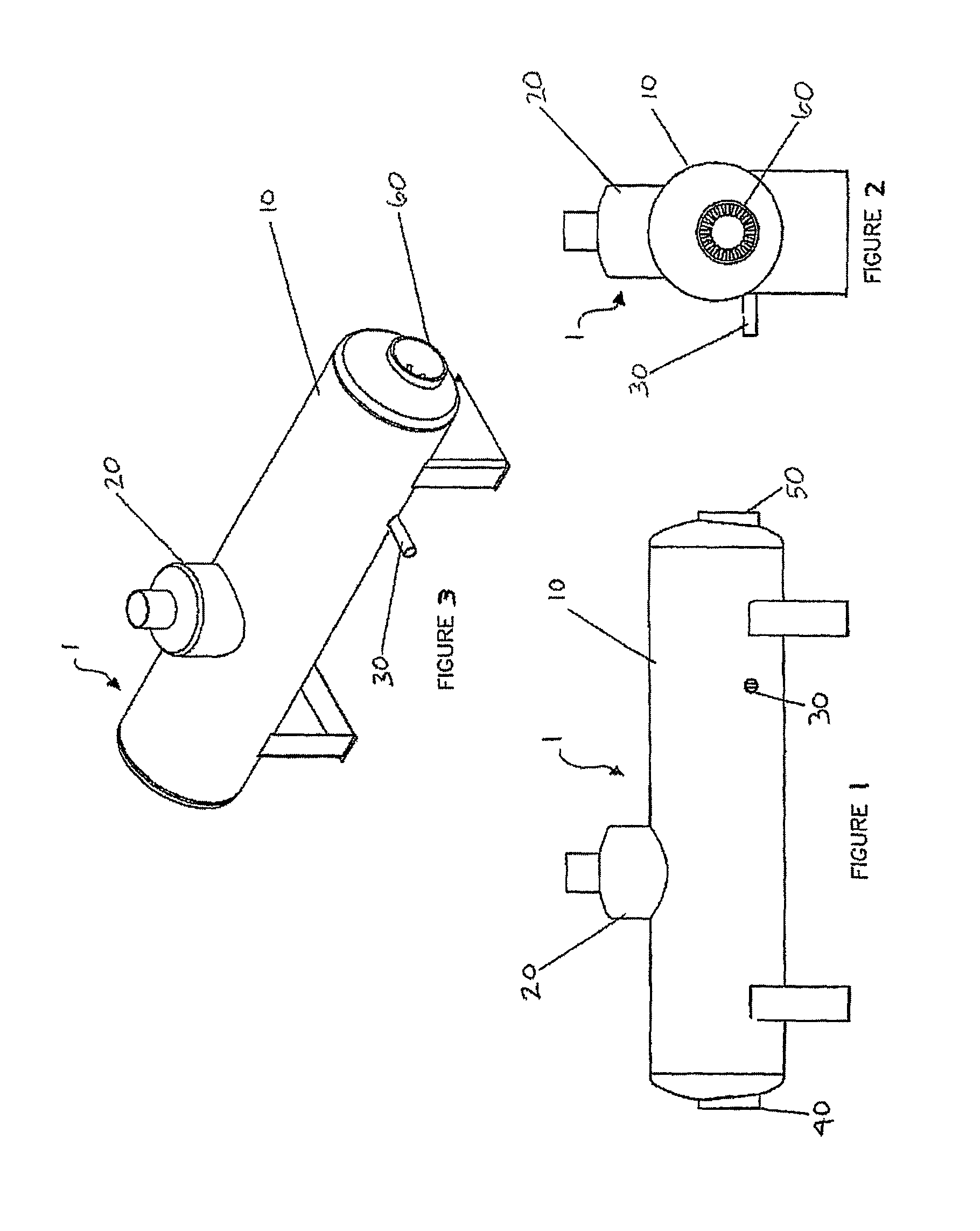
[0060]Referring now to FIGS. 13-18, a direct-fired boiler 200 is shown with a coiled enhanced conduit 260. The long axis of cylindrical vessel 210 is oriented vertically, rather than horizontally as in Example 1. Rather than completing a series of reversals in direction as in Example 1, enhanced conduit 260 is coiled within vessel 210, completing a total of three revolutions. Hot fluid enters boiler 200 through hot fluid inlet 240, passes through enhanced conduit 260, and exits through flue outlet 250. As in Example 1, enhanced conduit 260 contains a plurality of fins 280 located around its circumference and along its length. Fins 280 may be fastened to enhanced conduit 260 by any of a number of means described above.

example 3

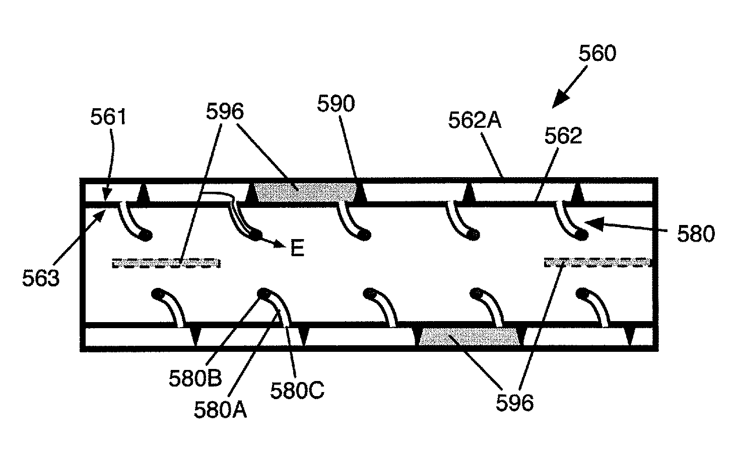
[0061]Referring to FIGS. 19-21, a 4-pass conduit 360 is shown. Unlike earlier-described embodiments, wherein a heat transfer medium sits within a vessel, the depicted embodiment incorporates a housing 360A around the apparatus 360. Housing 360A directs a heat transfer medium along an outer surface of a pass 362, 364, 366, 368 as the hot fluid is directed along an inner surface of the same pass. In some embodiments, such as that shown in FIG. 20, the apparatus has a “reverse flow,” wherein as the hot fluid enters first pass 362 (often a firetube), the heat transfer medium enters through a heat transfer medium inlet 368B at a distal end of the fourth pass housing 368A, flows in a direction substantially opposite that of the hot fluid, and exits through a heat transfer medium outlet 362B at a proximal end of the first pass housing 362A.

[0062]In the embodiment depicted in FIG. 19, three of the four passes 362, 364, 366 are enhanced, each containing a plurality of fins 380 extending thro...


PUM


Abstract

The invention provides high-efficiency heat transfer devices and apparatuses. In one embodiment, the invention includes a vessel capable of containing the heat transfer medium, a conduit extending through a wall of the vessel, the conduit having a first surface for contacting the heat transfer medium and a second surface for contacting a fluid within the conduit, a helical member residing around and along a length of the first surface of the conduit capable of angularly directing a flow of the heat transfer medium along the first surface of the conduit; and a plurality of fins helically arranged adjacent the helical member, each fin extending through a wall of the conduit and being capable of directing at least a portion of the heat transfer medium to an area within a radius of the conduit.

Description

CROSS-REFERENCE TO RELATED APPLICATIONS[0001]This application is a continuation-in-part of co-pending U.S. patent application Ser. No. 11 / 276,368, filed 27 Feb. 2006, which is hereby incorporated herein.BACKGROUND OF THE INVENTION[0002](1) Technical Field[0003]The present invention relates generally to a heat exchanger, and more specifically to a “direct-fired” or “indirect-fired” boiler for generating steam, hot water, hot oil, and hot molten metals.[0004](2) Related Art[0005]All boilers operate according to the physical sciences of thermodynamics and heat transfer. Essentially, forced hot gas is cooled within the boiler by transferring heat to a heat transfer medium, often water, to generate steam or hot water. Depending upon system requirements, direct-fired boilers and / or indirect-fired boilers are commonly placed in service to produce steam and hot water. In the case of a direct-fired boiler, a fueled burner or combustor is fired into the boiler, generating heat within the boil...

Claims


Application Information

Patent Timeline
Patent Type & Authority Patents(United States)
IPC IPC(8): F28D7/02F28F1/14F28F1/20F28F1/42F22B37/10F28F13/08F28F1/36F28F1/12F28D7/08
CPCF28D7/024F22B37/101F22B37/103F28D7/026F28D7/08F28D7/085F28F1/124F28F1/36F28F1/42F28F1/422F28F13/08F28F2215/06
Inventor OKONSKI, JR., JOHN E.OKONSKI, SR., JOHN E.
Owner OKONSKI JR JOHN E
Why Eureka
Try Eureka