Conveyor chain

a conveyor and belt module technology, applied in the field of conveyor chains, can solve the problems of increased sliding wear, increased sliding wear, and the above-described belts have problems with accelerated wear

Active Publication Date: 2006-11-23
TSUBAKIMOTO CHAIN CO
View PDF13 Cites 17 Cited by
  • Summary
  • Abstract
  • Description
  • Claims
  • Application Information

AI Technical Summary

Benefits of technology

[0008] In accordance with the instant invention, conveyor chains are provided which solve the above-mentioned problems. In accordance with one aspect of the instant invention, the conveyor chain of the instant invention comprises a number of chain links comprising a plurality of hinge portions in a zigzag formation which protrude from the front end and rear end edges. The

Problems solved by technology

This formation causes sliding wear between the belt module and the balls.
Because the materials of the belt module and the ball are the same, however, the contact surfaces between the belt module and ball have high affinity and are likely to adhere to each other, thereby resulting in increased sliding wear.
Therefore, the above described belts have proble

Method used


Image

  • Conveyor chain
  • Conveyor chain
  • Conveyor chain

Examples


example 1

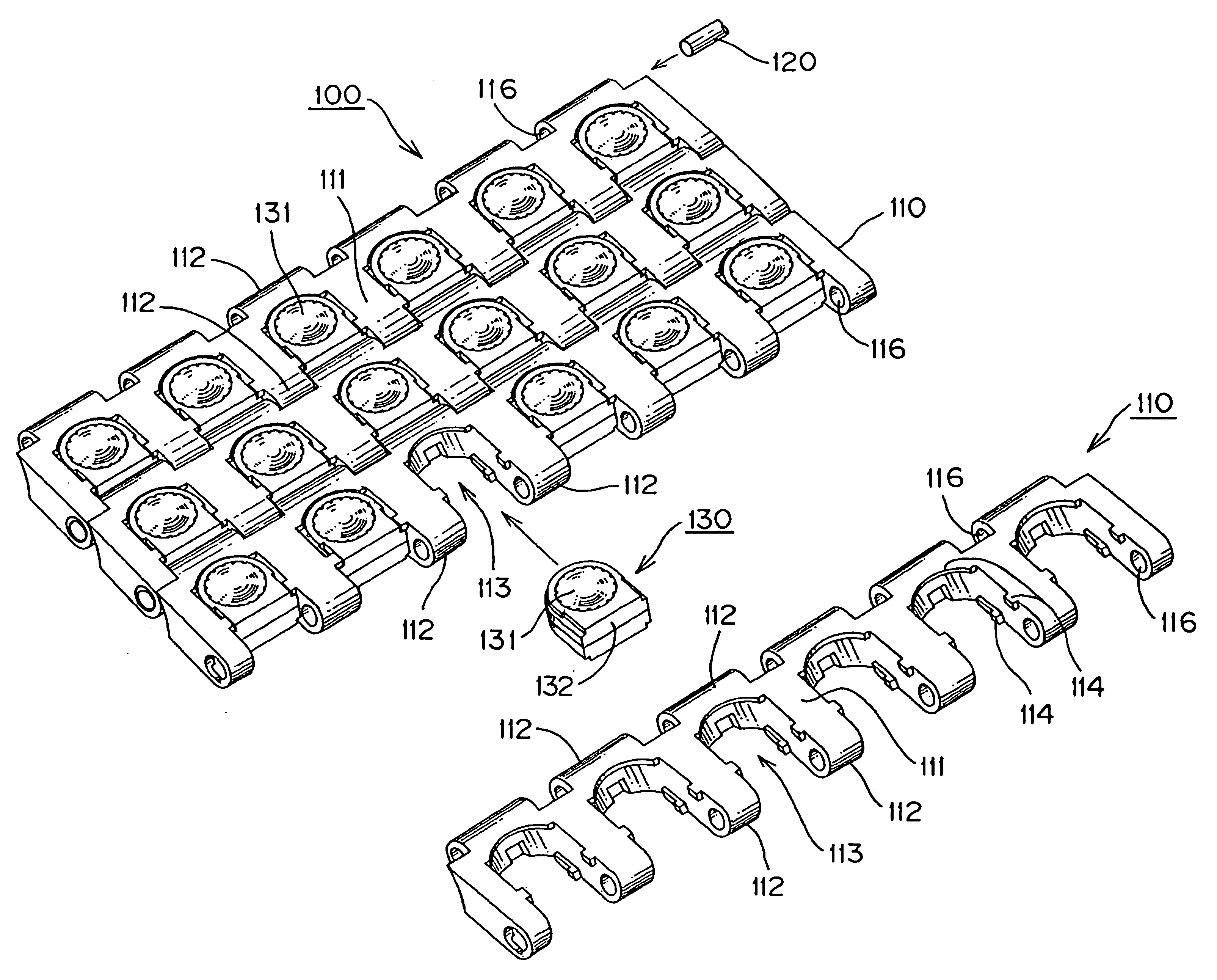
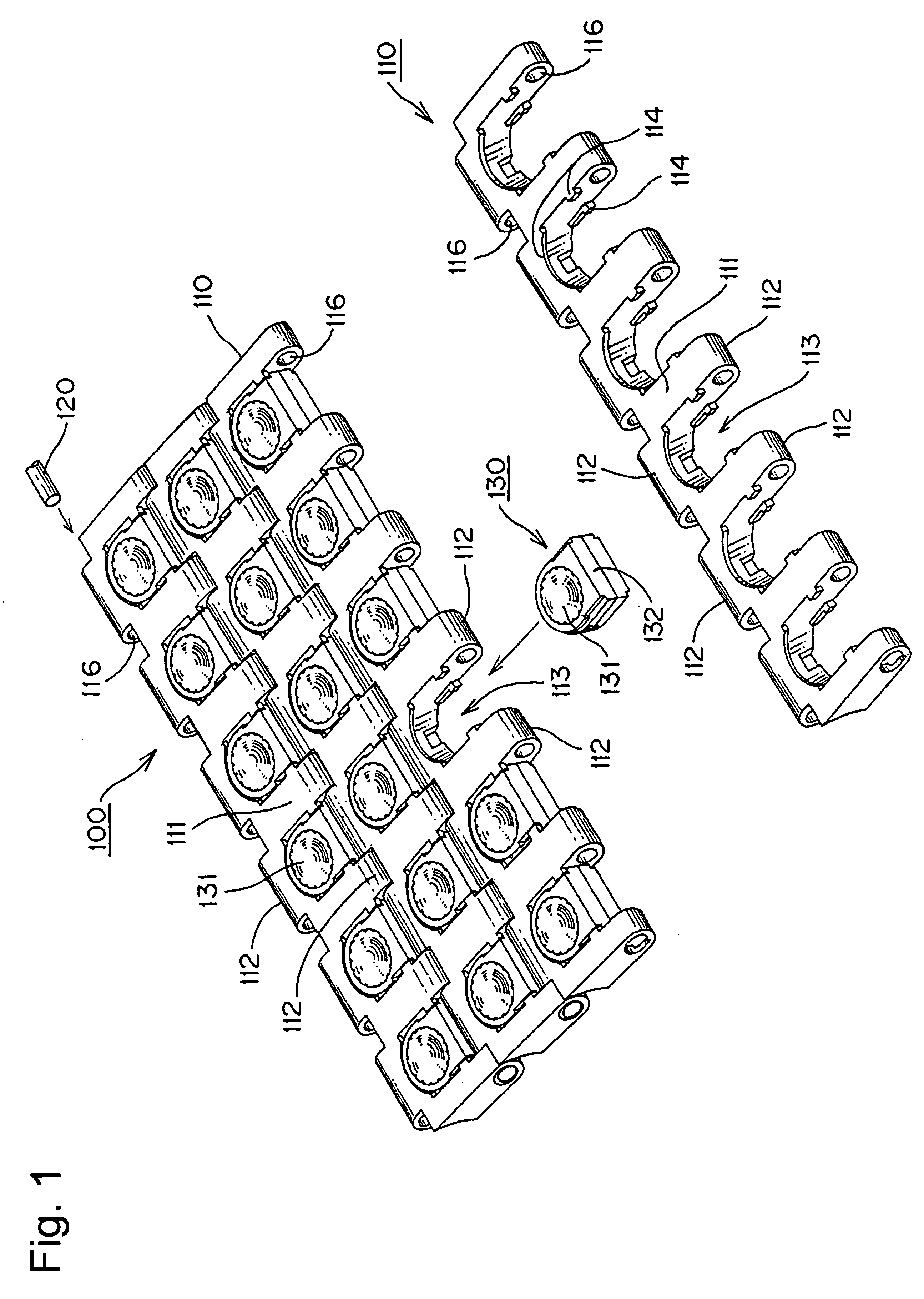
[0029] A first exemplary conveyor chain of the instant invention is described hereinbelow with reference to FIGS. 1 to 4.

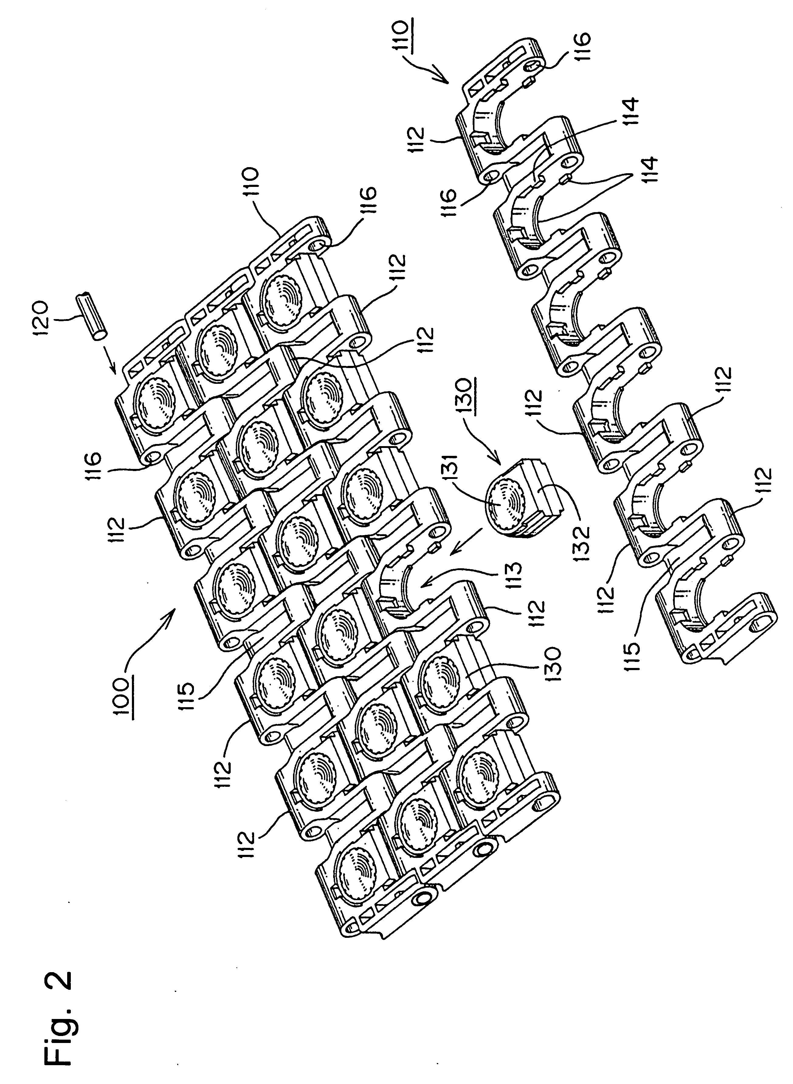
[0030]FIG. 1 is a schematic explanatory view of a part of a conveyor chain of the present example viewed from the surface side. FIG. 2 is a perspective view the conveyor chain of FIG. 1 viewed from the back surface side of the chain link. FIG. 3 shows the components of the ball unit assembly. FIG. 4 is an explanatory view showing an operation state of the conveyor chain.

[0031] A conveyor chain 100 of the present example, as shown in FIG. 1, comprises a number of chain links 110 longitudinally connected to each other by the insertion of the hinge pins 120 into pin holes 116 provided in hinge portions 112. A free ball 131 in a ball unit 130 is mounted into a unit mounting region 113 formed in the chain link. The free balls 131 are held by the chain links 110 and articles (e.g., box-shaped, plate-shaped, and the like) are conveyed by being loaded on the free balls ...

example 2

[0044] A second exemplary conveyor chain 200 of the instant invention is described hereinbelow with reference to FIG. 5.

[0045]FIG. 5 is a schematic explanatory view of a part of the conveyor chain, which is the present example, viewed from the surface side of the chain.

[0046] In the conveyor chain 200, ball holding portions 213 are integrally formed within a chain link 210. The chain link is made of polyacetal and the free bail 230 is made of polyamide.

[0047] It is noted that the functions of the free ball 230 are substantially the same as those of the free ball 131 of the first example.

[0048] As shown in FIG. 5, the conveyor chain 200 comprises a number of chain links 210 which are longitudinally connected to each other by inserting hinge pins 220 into pin holes 216 provided in hinge portions 212. A free ball 230 is held in a ball holding portion 213 formed in the chain link 210.

[0049] The chain link 210, as shown in FIG. 5, comprises a plurality of hinge portions 212 in a zig...


PUM


Abstract

Conveyor chains are provided which comprise free balls which are free to rotate in all directions thereby allowing for the stable conveyance of articles in any direction in the entire horizontal plane and at an increased speed in the direction of conveyance with reduced contamination in the conveyance environment. A conveyor chain 100 comprises a number of chain links 110 comprising a plurality of hinge portions 112 in a zigzag formation protruding from the front and rear end edges that are connected to each other in the longitudinal direction of the chain through hinge pins 120. Free balls 131 protrude from both the surface and back sides of the chain link 110 and are free to rotate while held in the chain link 110. Either the free balls 131 or ball holding portions 132, which hold the free balls 131, is made of polyacetal while the other is made of polyamide or polyester.

Description

[0001] This application claims priority under 35 U.S.C. § 119(a) to Japanese Patent Application 2005-150034, filed May 23, 2005. The foregoing application is incorporated by reference herein. FIELD OF INVENTION [0002] The present invention relates to conveyor chains suitable for loading and conveying articles having a flat bottom surface (e.g., box-shaped articles, plate-shaped articles, and the like). More specifically, the present invention relates to a conveyor chain comprising free balls which protrude from both the surface and back sides of the chain link. BACKGROUND OF THE INVENTION [0003] Conveyor belts for the conveyance of articles may comprise balls or rollers which can rotate. The articles can be quickly sorted during conveyance on such conveyor belts as they can be unloaded while being slid to a side of the conveyance line (see Japanese Laid-Open Patent Publication No. 2003-182829). [0004] In such a conveyor belt, the belt module comprises vertically laminated first and ...

Claims


Application Information

Patent Timeline
IPC IPC(8): B65G17/06
CPCB65G17/24B65G2207/30B65G2201/02B65G17/40
Inventor OZAKI, HAJIMESHIBAYAMA, KATSUTOSHIMURAKAMI, YOSHIHIRO
Owner TSUBAKIMOTO CHAIN CO
Why Eureka
Try Eureka