Magnetic assembly for a linear beam tube

a linear beam tube and magnetic assembly technology, applied in the direction of transit-tube circuit elements, waveguide devices, klystrons, etc., can solve the problems of density modulation of electron beams and integral cavity devices

Active Publication Date: 2006-11-23
E2V TECH (UK) LTD
View PDF4 Cites 0 Cited by
  • Summary
  • Abstract
  • Description
  • Claims
  • Application Information

AI Technical Summary

Benefits of technology

[0010] The invention resides in an RF window arrangement for an electron beam tube so arranged that the output coupler may extend into the interaction cavity whilst remaining outside the vacuum envelope of the electron beam tube. The preferred RF window arrangement is a ceramic dome which covers an output loop and provides an airtight seal to the vacuum within the tube whilst being substantially transparent to RF. While the preferred embodiment is a ceramic dome, other arrangements such as a closed short cylindrical arrangement may be appropriate in some applications.

Problems solved by technology

This causes density modulation of the electron beam.
We have further appreciated that this is relatively simple for external cavity devices in which the coupling loop is outside the vacuum envelope, but is problematic for prior integral cavity devices.

Method used


Image

  • Magnetic assembly for a linear beam tube
  • Magnetic assembly for a linear beam tube
  • Magnetic assembly for a linear beam tube

Examples


Embodiment Construction

[0018] The embodiment of the invention described is an Inductive Output Tube (IOT). However, it would be appreciated to the skilled person that the invention applies equally to other linear beam devices such as travelling wave tubes and Klystrons.

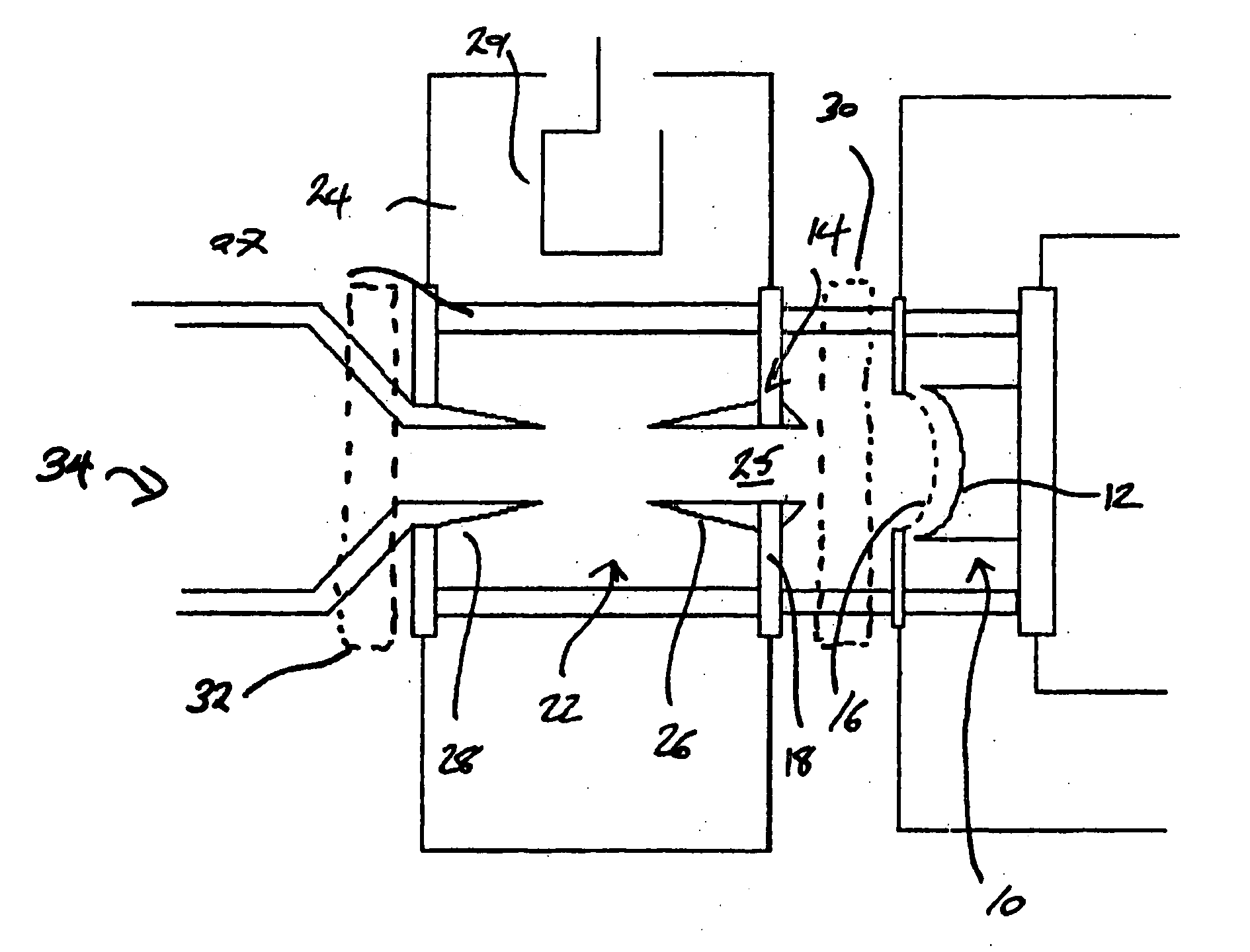
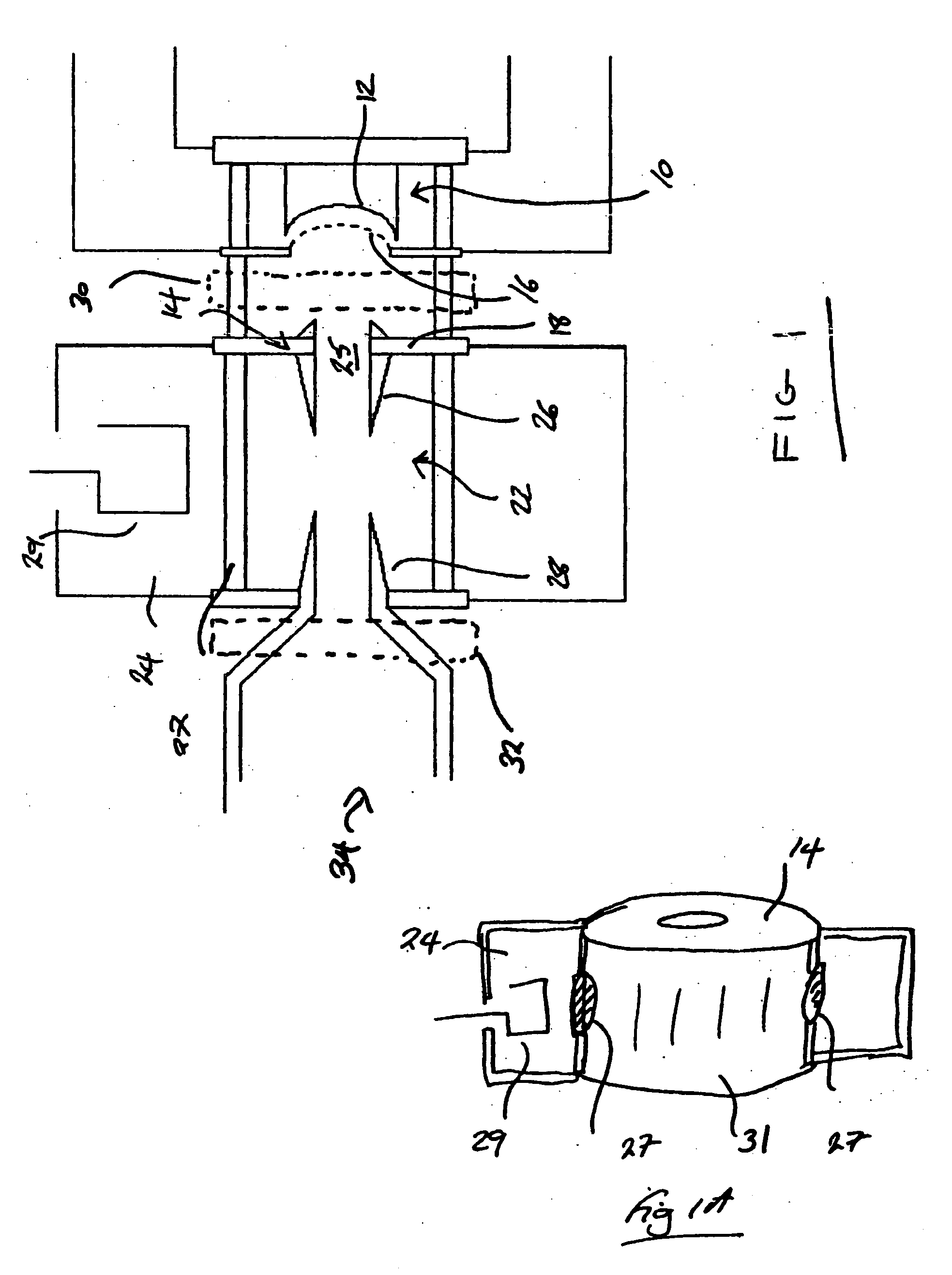
[0019] A known external output cavity IOT is first described, shown in FIG. 1, and comprises an electron gun 10 for generating an electron beam. The electron beam is created from a heated cathode 12 held at a negative beam potential of around −36 kV and accelerated towards and through an aperture in a grounded anode 14 formed as part of a first portion of a drift tube 22 described later. In normal use, the electron gun 10 is uppermost.

[0020] A grid 16 is located close to and in front of the cathode and has a DC bias voltage of around −80 volts relative to the cathode potential applied so that, with no RF drive a current of around 500 mA flows. The grid itself is clamped in place in front of the cathode (supported on a metal cylinder) and ...


PUM


Abstract

An electron beam tube device such as an inductive output tube of the integral cavity type has a RF window which re-enters the interaction space within the cavity thereby defining a space that is within the interaction cavity but is outside the vacuum. An output coupler in the form of an output coupling loop protrudes into this space and thus couples with the electromagnetic field within the interaction space, whilst remaining outside the vacuum envelope. This allows the coupling loop to be adjusted without any additional seal arrangement between the coupling loop and walls of the output cavity.

Description

CROSS-REFERENCE TO RELATED APPLICATION [0001] This application claims the priority of British Patent Application No. 0503543.1 filed on Feb. 21, 2005, the subject matter of which is incorporated herein by reference. BACKGROUND OF THE INVENTION [0002] The present invention relates to linear beam tube devices, in particular, to electron beam tube devices such as IOTs and Klystrons. [0003] Linear beam tube devices such as electron beam tube devices are used for the amplification of RF signals. There are various types of linear electron beam tube device known to those skilled in the art, two examples of which are the klystron and the Inductive Output Tube (IOT). Linear electron beam tubes incorporate an electron gun for the generation of an electron beam of an appropriate power. The electron gun includes a cathode heated to a high temperature so that the application of an electric field between the cathode and an anode results in the emission of electrons. Typically, the anode is held a...

Claims


Application Information

Patent Timeline
Patent Type & Authority Applications(United States)
IPC IPC(8): H01J25/34H01J23/10H01J25/04
CPCH01J25/04H01J23/10H01J23/46
Inventor AITKEN, STEVEN
Owner E2V TECH (UK) LTD
Why Eureka
Try Eureka