DC-DC converter having protective function of over-voltage and over-current and led driving circuit using the same

a technology of over-voltage and over-current protection and driving circuit, which is applied in the direction of electric variable regulation, process and machine control, instruments, etc., can solve the problems of low color reproducibility, prone to environmental pollution, slow response rate, etc., and achieve the effect of preventing circuit damag

Active Publication Date: 2006-11-23
SAMSUNG ELECTRONICS CO LTD
View PDF3 Cites 82 Cited by
  • Summary
  • Abstract
  • Description
  • Claims
  • Application Information

AI Technical Summary

Benefits of technology

[0015] The present invention has been made to solve the foregoing problems of the prior art and it is therefore an object of the present invention to provide a DC-DC converter which detects over-current and over-voltage due to disconnection or short circuit of a load to halt the operation of a circuit in advance, thereby preventing damage to the circuit.

Problems solved by technology

Thus it has drawbacks in that it is prone to environmental pollution, has a slow response rate, has low color reproducibility and is not appropriate for miniaturization of an LCD panel.
In an LED driving circuit using such a buck DC-DC converter, when both ends of the LED array 11 are short-circuited due to abnormality in the external environment of the circuit or in the driving circuit itself, over-current may run on the circuit, damaging the diode D and the switch 12.
The LED included in the LED array 11 can also be damaged by the over-current if it exceeds the rated current of the LED array 11.
Furthermore, the accumulated current may flow from Switch Mode Power Supply (SMPS), which supplies the direct current Vin, to the driving circuit, causing a more serious problem.
Thus, due to counter electromotive force of the inductor, both ends of the LED array 11 are applied with a voltage several times higher than the inductor voltage during a normal operation and the input voltage, resulting damage to the device by over-voltage.

Method used


Image

  • DC-DC converter having protective function of over-voltage and over-current and led driving circuit using the same
  • DC-DC converter having protective function of over-voltage and over-current and led driving circuit using the same
  • DC-DC converter having protective function of over-voltage and over-current and led driving circuit using the same

Examples


Embodiment Construction

[0035] Preferred embodiments of the present invention will now be described in detail with reference to the accompanying drawings. It is intended, however, that unless particularly specified, dimensions, materials, relative positions and so forth of the constituent parts in the embodiments shall be interpreted as illustrative only not as limitative of the scope of the present invention. These embodiments are provided so that this disclosure will be thorough and complete, and will fully convey the scope of the invention to those skilled in the art. In the drawings, the shapes and dimensions are exaggerated for clarity, and the same reference numerals are used throughout to designate the same or similar components.

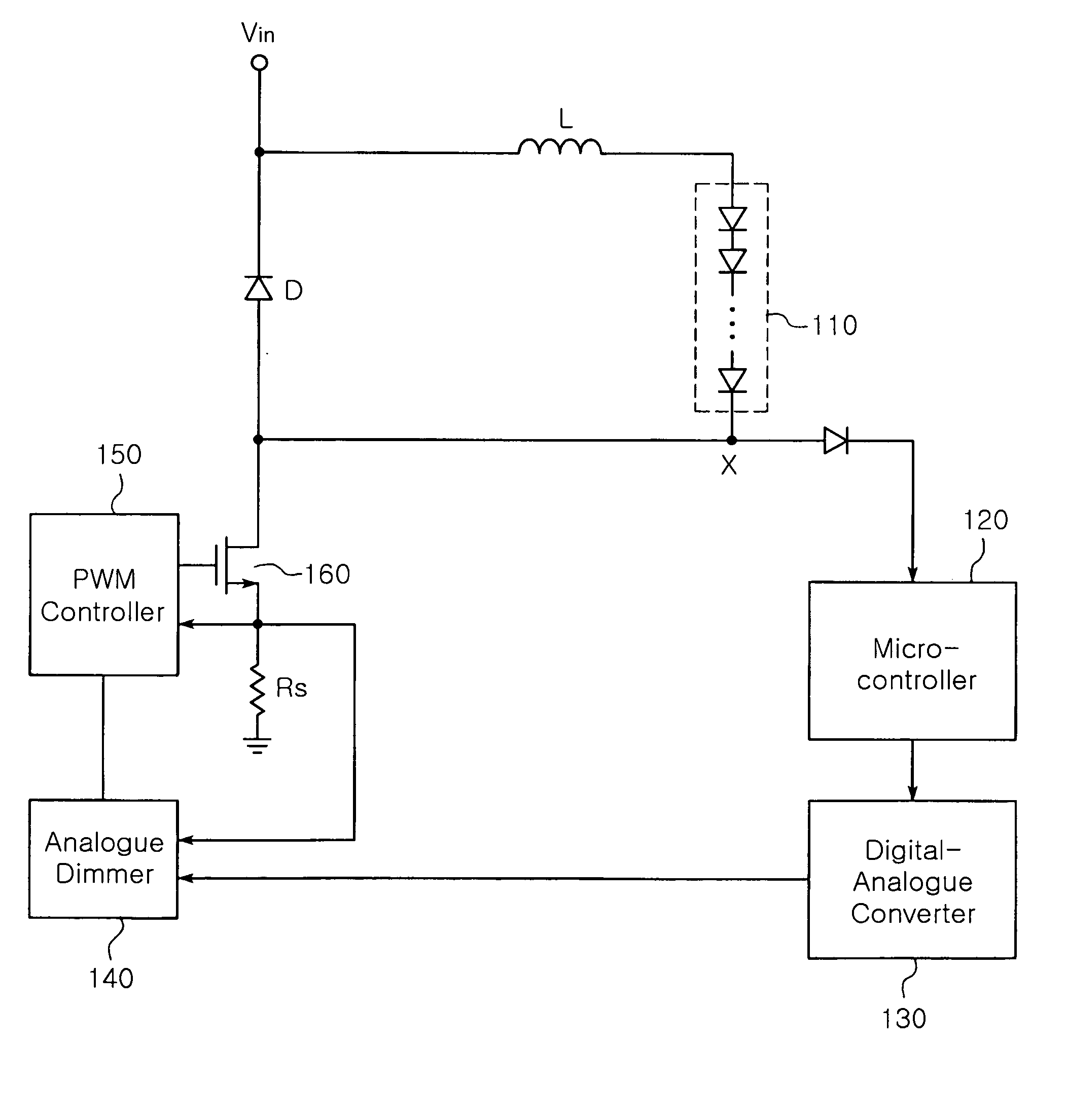
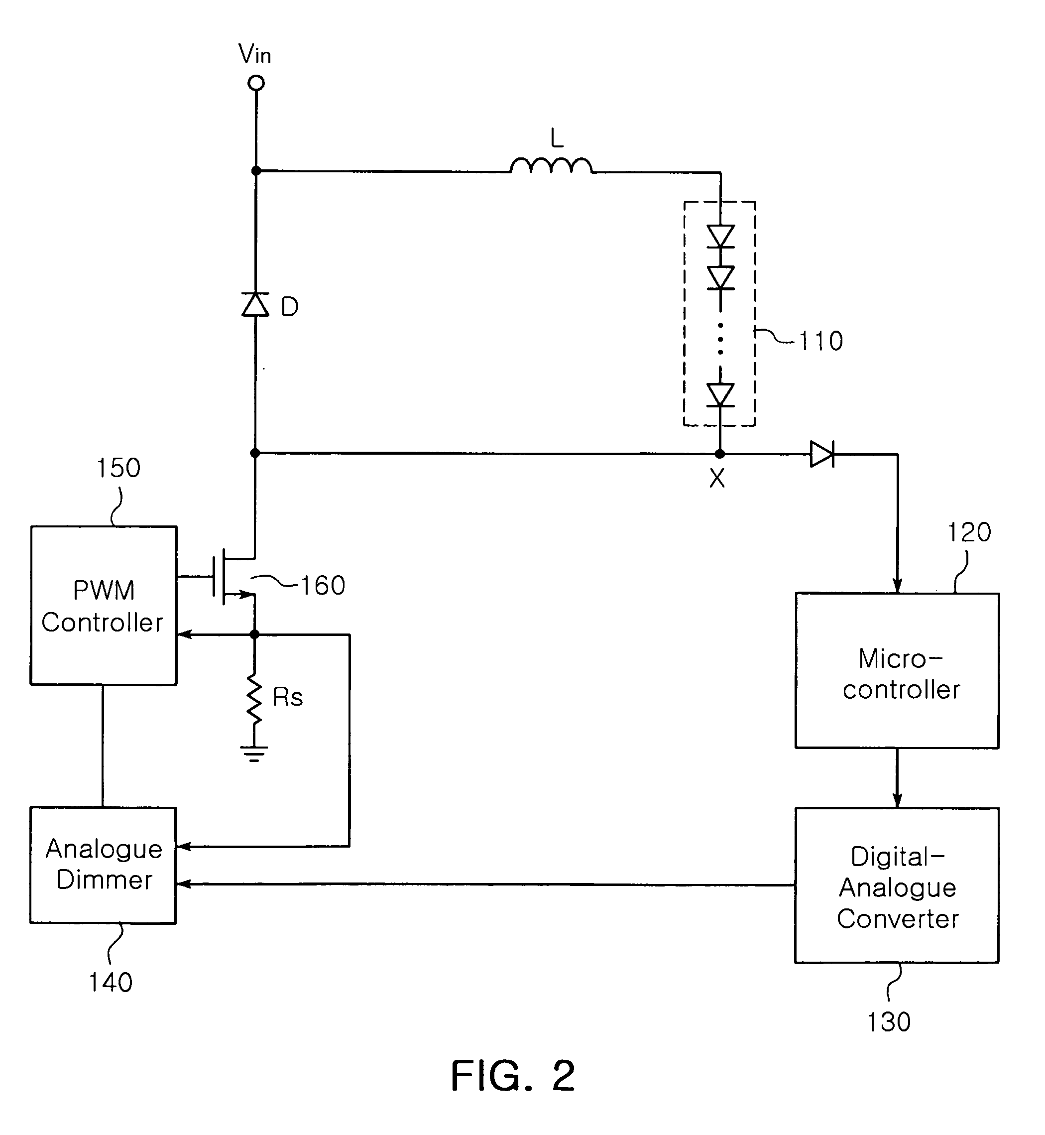
[0036]FIG. 2 is a circuit diagram illustrating a DC-DC converter according to an embodiment of the present invention. The DC-DC converter illustrated in FIG. 2 is an example of a buck DC-DC converter. Referring to FIG. 2, the DC-DC converter according to an embodiment of th...


PUM


Abstract

The invention relates to a DC-DC converter having over-current/over-voltage protection function and an LED driving circuit using the same. The DC-DC converter adjusts a width of a switching pulse outputted from a Pulse Width Modulation (PWM) controller to control on/off durations of a switch, thereby providing a controlled level of voltage to a load. The DC-DC converter includes a microcontroller for detecting a voltage, and if the detected voltage is greater than a reference voltage, generating an alarm signal. The DC-DC converter further includes a digital-analogue converter for outputting a voltage of 0V and an analogue dimmer for generating a control signal that changes an ‘on’ duration of the switching pulse outputted from the PWM controller to 0 and providing the control signal to the PWM controller.

Description

CLAIM OF PRIORITY [0001] This application claims the benefit of Korean Patent Application No. 2005-41525 filed on May 18, 2005, in the Korean Intellectual Property Office, the disclosure of which is incorporated herein by reference. BACKGROUND OF THE INVENTION [0002] 1. Field of the Invention [0003] The present invention relates to a DC-DC converter and a light emitting diode (LED) driving circuit using the same. More particularly, the invention relates to a Pulse Width Modulation (hereinafter referred to as PWM) based DC-DC converter, which immediately blocks over-current or over-voltage due to short-circuit or disconnection from being applied to the DC-DC converter in order to protect a circuit, and an LED driving circuit using the same. [0004] 2. Description of the Related Art [0005] In general, a Cold Cathode Fluorescent Lamp (CCFL, hereinafter referred to as CCFL) used for a light source of a Liquid Crystal Display (LCD, hereinafter referred to as LCD) uses mercury gas. Thus it...

Claims


Application Information

Patent Timeline
Patent Type & Authority Applications(United States)
IPC IPC(8): H05B37/02
CPCH05B33/0857Y02B20/341H05B33/0887H05B45/20Y02B20/30H05B45/54H02M3/157
Inventor LEE, SANG YUN
Owner SAMSUNG ELECTRONICS CO LTD
Why Eureka
Try Eureka