Display system and method using a solid state laser

a laser and solid state technology, applied in the field of display systems and methods using solid state lasers, can solve the problems of excessive weight, high power consumption, and several handicaps of the cr

Inactive Publication Date: 2006-11-23
AVAGO TECH ECBU IP (SINGAPORE) PTE LTD
View PDF9 Cites 73 Cited by
  • Summary
  • Abstract
  • Description
  • Claims
  • Application Information

AI Technical Summary

Problems solved by technology

However, the CRT suffers from several handicaps such as large bulk, excessive weight, high power consumption, and the presence of hazardous voltages.
Consequently, the CRT is used only where such handicaps are acceptable and has, unfortunately, been found inappropriate in many modern applications.
For example, a CRT cannot be readily integrated into small hand-held devices such as a personal digital assistant (PDA) or a cellular phone.
Unfortunately, LCD displays may offer poor display visibility under certain ambient light conditions.
Unfortunately, the halogen bulb is an inefficient light source that suffers in comparison to a solid-state light source.

Method used


Image

  • Display system and method using a solid state laser
  • Display system and method using a solid state laser
  • Display system and method using a solid state laser

Examples


Embodiment Construction

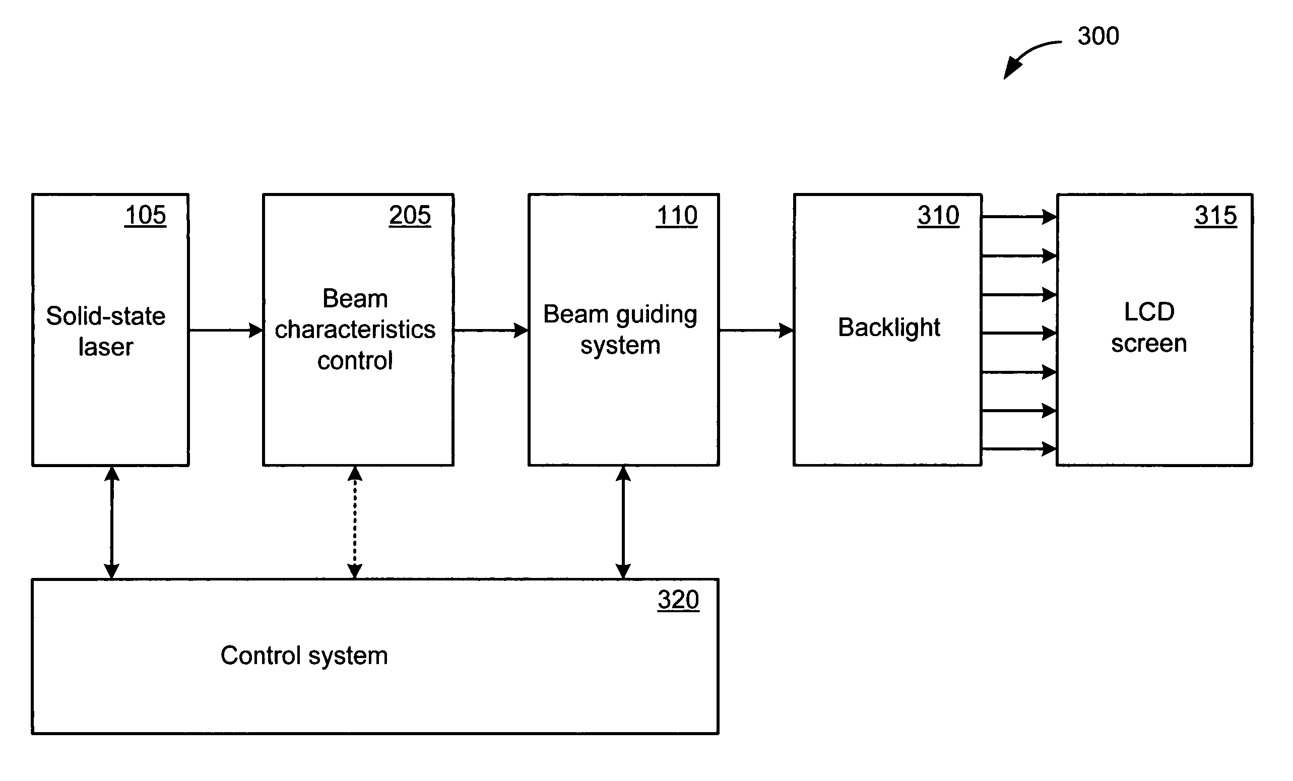
[0022] The various embodiments in accordance with the invention relate to a display system that uses a solid state laser to excite a suitable phosphor to emit light. In one exemplary embodiment, a solid state laser generates a laser beam in an approximate wavelength range between 330 nm and 440 nm and uses the laser beam to excite the phosphor of a display screen. The excited phosphor emits light in an approximate wavelength range between 450 nm and 650 nm.

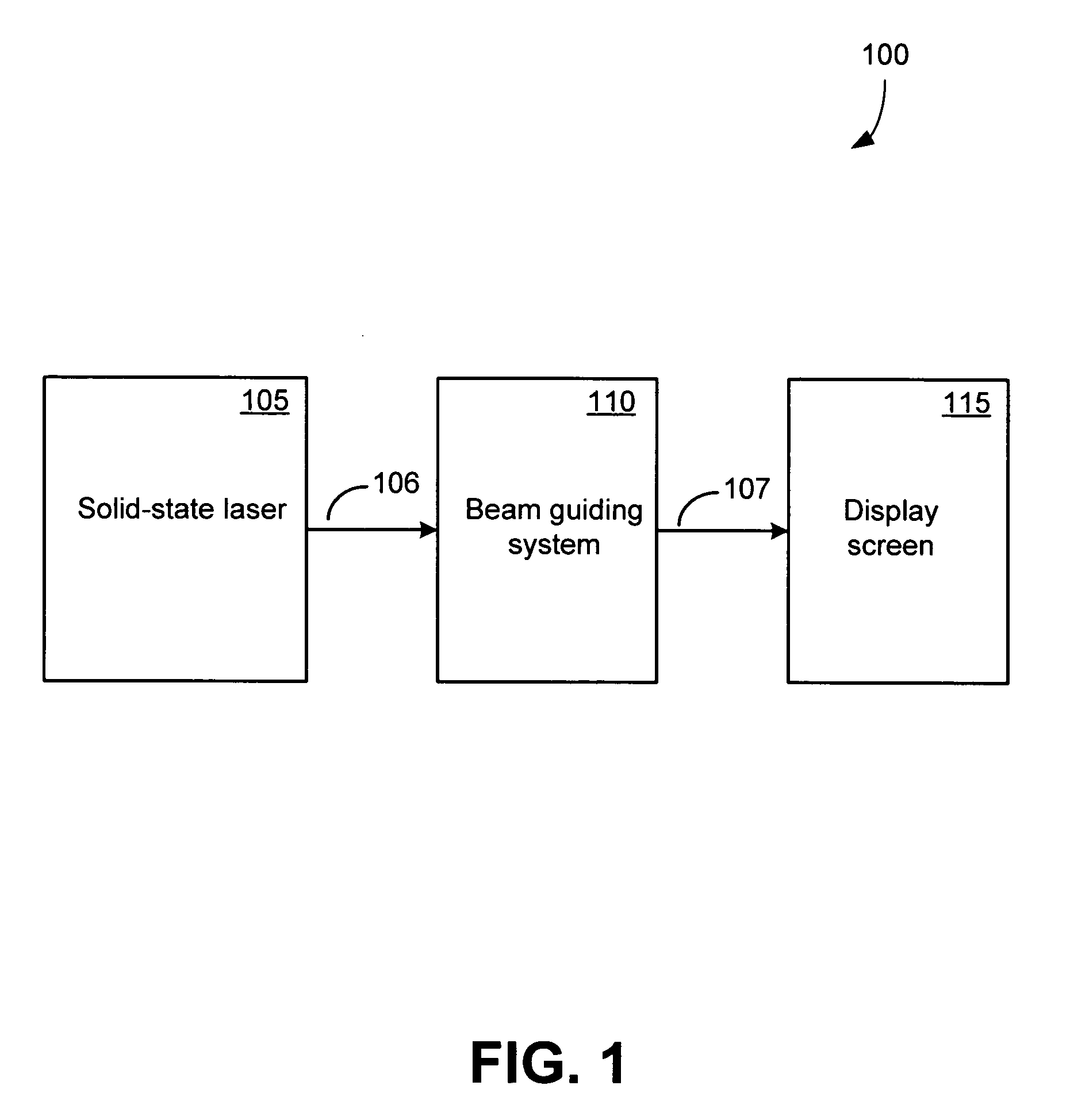
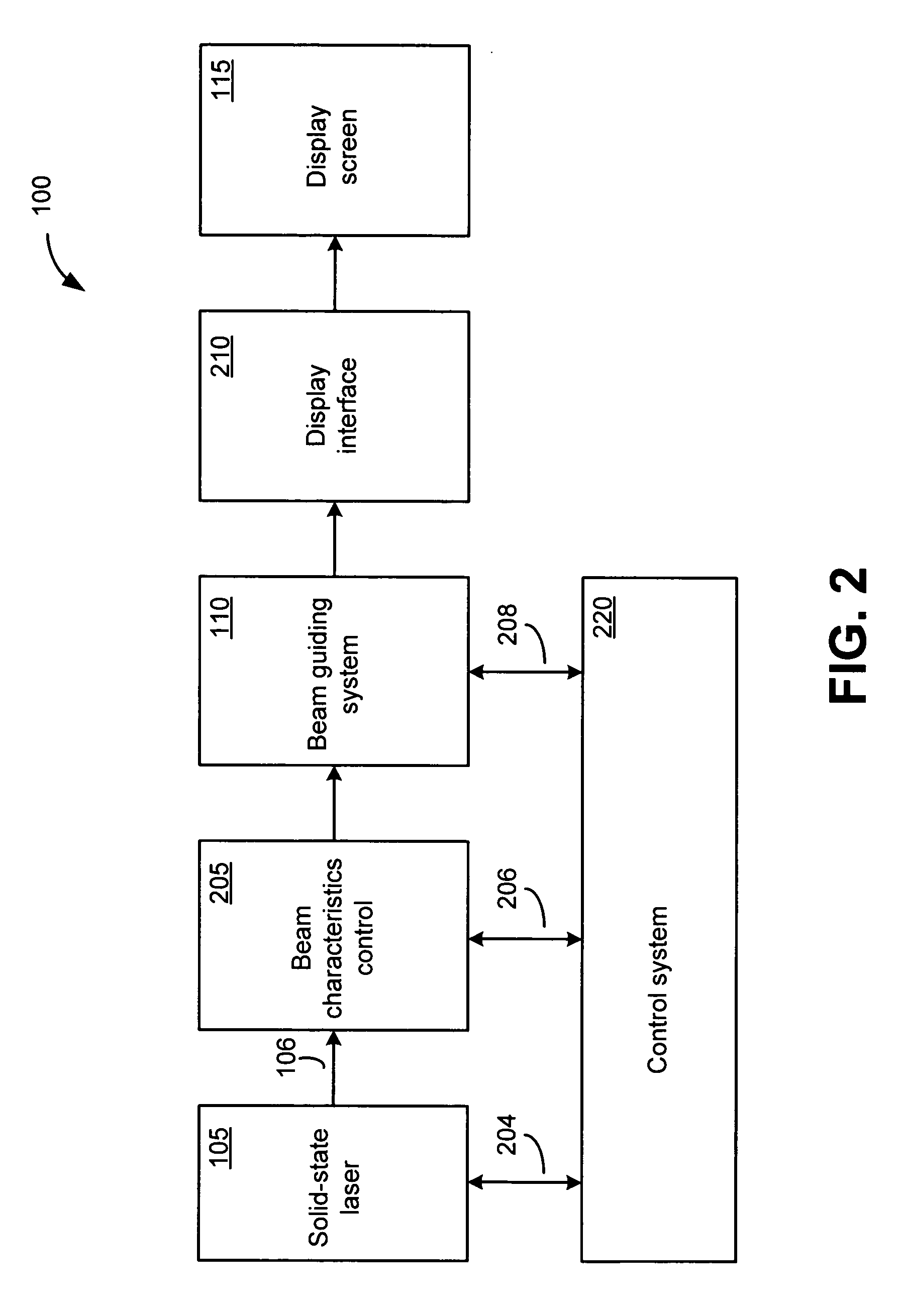
[0023]FIG. 1 shows a first exemplary embodiment of display system 100 in accordance with the invention that includes a solid state laser 105 optically coupled to a beam guiding system 110, which is in turn optically coupled to a display screen 115. In this exemplary embodiment, solid state laser 105 is an edge-emitting semiconductor laser composed of materials such as Aluminum, Gallium, Indium, and Nitrogen. Typically, solid state laser 105 is composed of several discrete layers of material that are formed upon a suitable substra...


PUM

PropertyMeasurementUnit
operating wavelengthsaaaaaaaaaa
wavelength rangeaaaaaaaaaa
first operating wavelengthaaaaaaaaaa

Abstract

A display system in accordance with the present invention includes a display screen having a phosphor that emits light in a wavelength range from about 450 nm to about 650 nm when excited by a laser beam. The laser beam is generated by a solid-state laser having an operating wavelength range from about 330 nm to about 440 nm.

Description

DESCRIPTION OF THE RELATED ART [0001] Electronic displays are implemented using various technologies such as liquid crystal display (LCD) technology, light emitting diode (LED) technology, and phosphor radiation technology. Phosphor radiation technology is an old and well-known technology that is best exemplified by a cathode ray tube (CRT). [0002] The raster scan mode of the CRT typically conforms to one or more widely accepted scanning standards thereby ensuring compatibility among various components as well as a uniform level of picture quality among displays manufactured by various manufacturers. [0003] However, the CRT suffers from several handicaps such as large bulk, excessive weight, high power consumption, and the presence of hazardous voltages. Consequently, the CRT is used only where such handicaps are acceptable and has, unfortunately, been found inappropriate in many modern applications. For example, a CRT cannot be readily integrated into small hand-held devices such a...

Claims


Application Information

Patent Timeline
Patent Type & Authority Applications(United States)
IPC IPC(8): G02F1/1335
CPCG02B26/101G02F2/02G09G3/02G09G3/3406H04N9/3141G09G3/3611G09G2310/0224H04N9/3129G09G3/342G02F1/13
Inventor LESTER, STEVEN D.BOUR, DAVID P.CORZINE, SCOTT W.
Owner AVAGO TECH ECBU IP (SINGAPORE) PTE LTD
Why Eureka
Try Eureka