Backlight and liquid crystal display device

a liquid crystal display and backlight technology, applied in the direction of instruments, lighting and heating apparatus, planar/plate-like light guides, etc., can solve the problems of low quantity of light, red color reproducibility, color reproducibility difficulties, etc., and achieve the effect of high light efficiency and higher light efficiency

Active Publication Date: 2006-11-23
HANNSTAR DISPLAY CORPORATION
View PDF4 Cites 87 Cited by
  • Summary
  • Abstract
  • Description
  • Claims
  • Application Information

AI Technical Summary

Benefits of technology

[0024] Since the backlight described above is used in the present invention, a high-quality image can be displayed because there is no nonuniformity of brightness and color, and uniform light can be supplied to a liquid crystal panel.
[0025] In accordance with the present invention, first and second light guide plates for mixing colors are disposed on both sides of a light source. Therefore, a thinner, more lightweight backlight with high light efficiency can be obtained without nonuniformity of luminescent color and brightness, and a backlight with higher light efficiency can be obtained.

Problems solved by technology

However, the light emission of the LED is mainly an artificial white light that is obtained by coating a blue LED with a YAG fluorophor, and there are difficulties in color reproducibility, and the reproducibility of red colors in particular.
However, not only do LEDs have difficulty with color reproducibility, but also the quantity of light is low, the cost is higher than a cold cathode fluorescent lamp, and there are other problems.
Therefore, there are few opportunities to use LEDs in monitors and TV applications.
However, the prior art described above has the following problems.
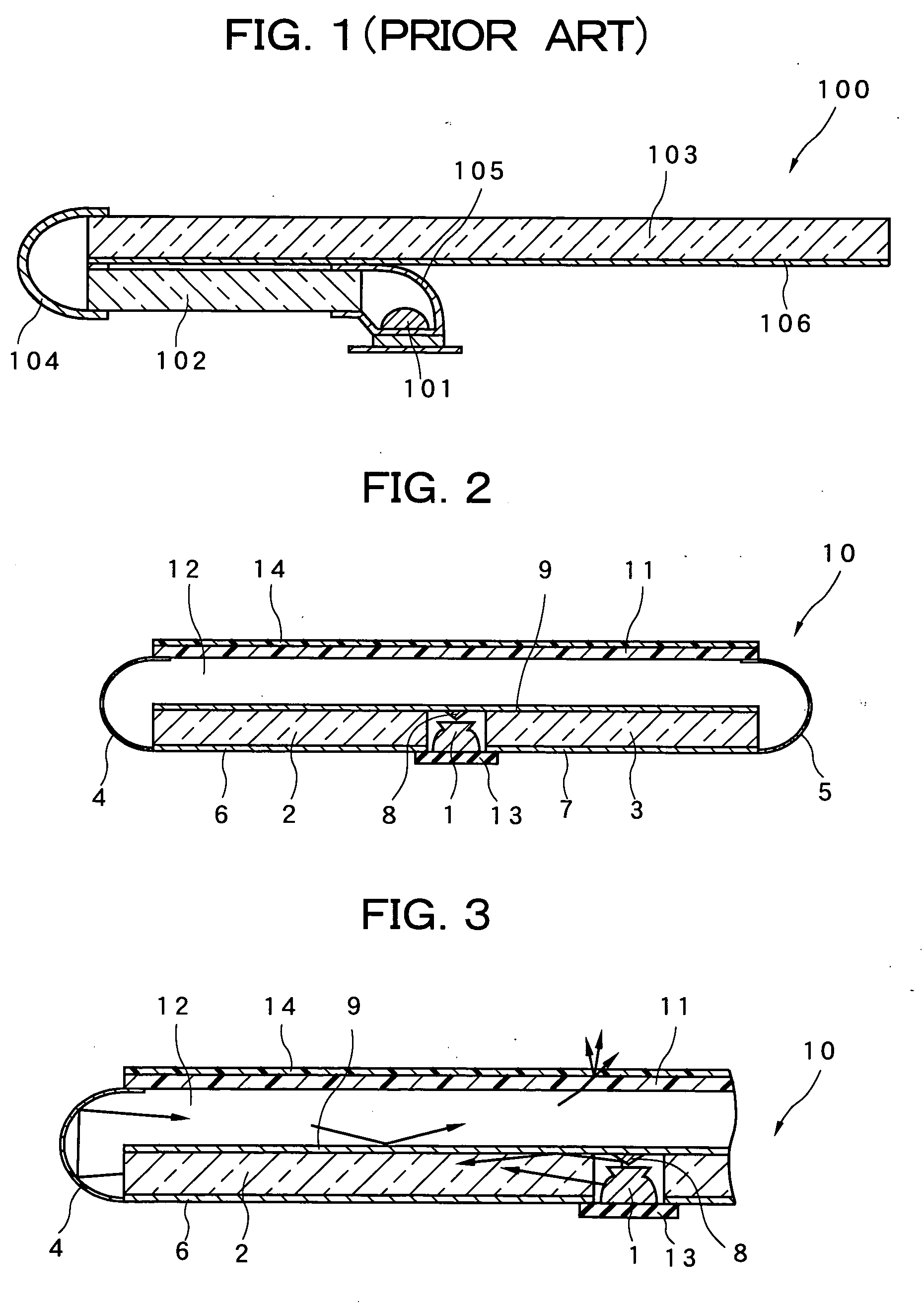
Therefore, there is a problem in that the mass of the light guide plate becomes several times greater than an ordinary edge-type backlight in which a cold cathode fluorescent lamp or the like is used and in which the light of tube is caused to directly enter the light guide plate, and the overall weight is increased.
The backlight 100 also has a problem in that there are incident and excident planes of the light guide plate 102, the incident plane of the light guide plate 103, and many other interfaces between air and physical objects, causing optical loss to occur at the interfaces and the efficiency of the light to decrease.
The backlight of Japanese Laid-Open Patent Application No. 2004-158336 has the effect of improving brightness nonuniformity and color nonuniformity, but there is a problem in that there are conversely a large number of components and increased external dimensions, particularly thickness.

Method used


Image

  • Backlight and liquid crystal display device
  • Backlight and liquid crystal display device
  • Backlight and liquid crystal display device

Examples


examples

[0063] The lens diameter D, light guide plate thickness T, distance between light guide plates L, curved surface radius R, R / D, D−2, and D+2 were set as shown in Table 1 in the backlight 60 of the sixth embodiment, and a simulated calculation was carried out. TABLE 2 shows the results of verifying by simulation the ratio of the luminous flux emitted from the reflector-side end face of the first and second light guide plates 2 and 3, and the ratio of the luminous flux incident on the reflector-side end face of the third light guide plate 15, per meter of the total luminous flux emitted from all the LEDs at the stated parameters. However, in the backlight of reference example 2, the cross-sectional shape of the reflective surface has a triangular shape in which the apex is down and the bottom side is up. The length of the two sides from the apex of the triangle is 3 mm. Other constituent elements are the same as the sixth embodiment described above. Also, the examples are configured s...


PUM


Abstract

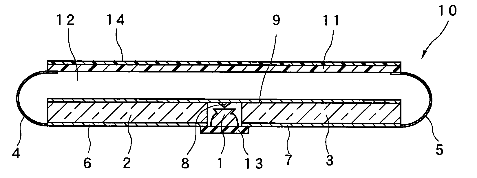
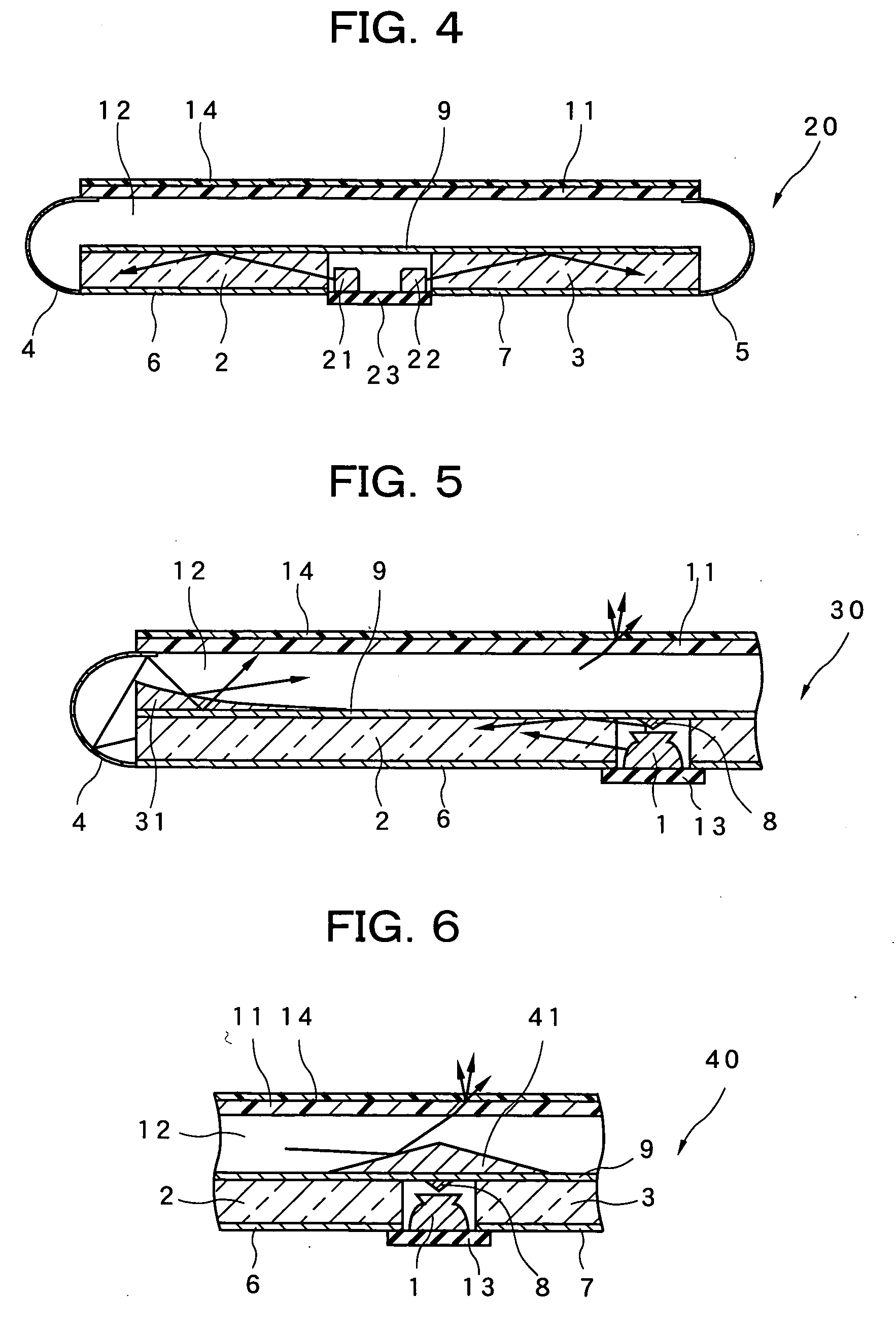
A plurality of LEDs are arrayed in a single row between the opposing end faces of a pair of first and second light guide plates that are disposed so that the end faces thereof face each other. A reflective sheet is disposed on the lower surfaces of the pair of first and second light guide plates, and a separation plate is disposed so as to cover the upper surfaces of the first and second light guide plates and the gap therebetween. A reflecting body for guiding light emitted upward from the LEDs to the first and second light guide plates is disposed in the area immediately above the LEDs on the lower surface of the separation plate. A diffusion plate is disposed with a fixed gap above the separation plate, and a hollow area is formed between the diffusion plate and the separation plate. Reflectors for causing light emitted from the first and second light guide plates to enter the hollow area are disposed at the end faces of the first and second light guide plates that face the LEDs. A thin, lightweight, and highly efficient backlight and liquid crystal display device can thereby be obtained without nonuniformity of color and brightness attributable to the LEDs.

Description

BACKGROUND OF THE INVENTION [0001] 1. Field of the Invention [0002] The present invention relates to a backlight which uses a light-emitting diode or the like as a light source and which is used in display devices, and to a liquid crystal display device provided with the backlight. [0003] 2. Description of the Related Art [0004] Conventionally, cold cathode fluorescent lamps are principally used as the light source for a backlight of a liquid crystal display device, but a cold cathode fluorescent lamp requires a dedicated lighting circuit that requires the use of high voltage. Therefore, an LED (Light Emitting Diode) is used as a light source in mobile phones, PDAs (Personal Digital Assistant), and other small applications in particular. However, the light emission of the LED is mainly an artificial white light that is obtained by coating a blue LED with a YAG fluorophor, and there are difficulties in color reproducibility, and the reproducibility of red colors in particular. It is ...

Claims


Application Information

Patent Timeline
Patent Type & Authority Applications(United States)
IPC IPC(8): F21V7/04
CPCG02B6/0018G02B6/0021G02B6/0078G02B6/0076G02B6/0031G02F1/1335
Inventor BABA, MASATAKE
Owner HANNSTAR DISPLAY CORPORATION
Why Eureka
Try Eureka