
Telescoping closed-tube sampling assembly

a closed-tube sampling and assembly technology, applied in the field of clinical diagnostic analyzers, can solve the problems of reducing the effectiveness and efficiency of sampling and analysis operations, presenting cost containment and biohazard issues in the laboratory, and blocking the sample aspirator

Active Publication Date: 2006-11-23
INSTR LAB
View PDF84 Cites 77 Cited by
  • Summary
  • Abstract
  • Description
  • Claims
  • Application Information

AI Technical Summary

Benefits of technology

[0021] In one embodiment, the clinical diagnostic analyzer according to the invention includes a spring operatively joined to the first tube to effect movement of the first tube. The first tube may further feature one or more detents for positioning the first tube in its ver

Problems solved by technology

Blood and other bodily fluids handled in large quantities by medical laboratories for processing and testing present cost containment and biohazard issues for the laboratory.
Currently available commercial sample analyzers capable of piercing sealed containers have several disadvantages that reduce the effectiveness and efficiency of the sampling and analysis operations.
The use of the sample aspirator in the dual mode may cause blockage of the sample aspirator if fragments of the seal enter the tip of the aspirator or the venting apertures disposed on the sample aspirator.
Additionally, even if a separate piercing apparatus is used to break the frangible seal, when the sample aspirator alone subsequently enters the perforated seal, debris from the seal can block the sample aspirator tip and / or any venting ports disposed thereon, thus reducing the accuracy of the sample volume aspirated, and potentially damaging the sample aspirator.
Clogged venting ports and aspirator tips increase the risk of cross-contamination of patient samples and also require that more time be dedicated to cleaning of the apparatus, thus increasing throughput times and decreasing the effectiveness of the analyzer.
These movements increase the throughput time of the sample analyzer, thus decreasing its efficiency.
In addition, currently available sample analyzers may only be able to aspirate sample from one type of vial or sample container at a time.
The inability of a sample analyzer to process different sized vials in the same batch negatively affects the throughput time of the analyzer, decreasing its efficiency.

Method used


Image

  • Telescoping closed-tube sampling assembly
  • Telescoping closed-tube sampling assembly
  • Telescoping closed-tube sampling assembly

Examples


Embodiment Construction

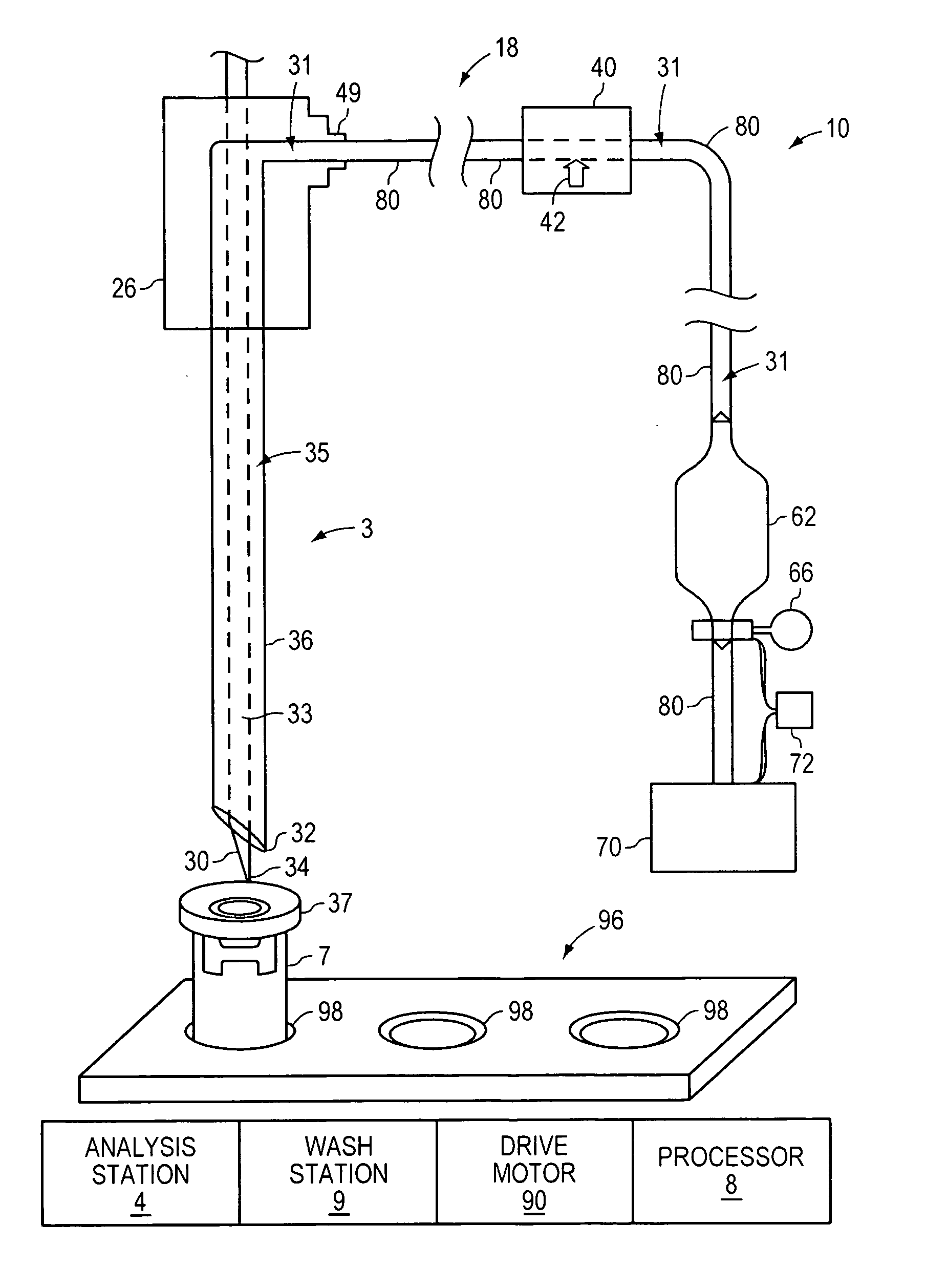
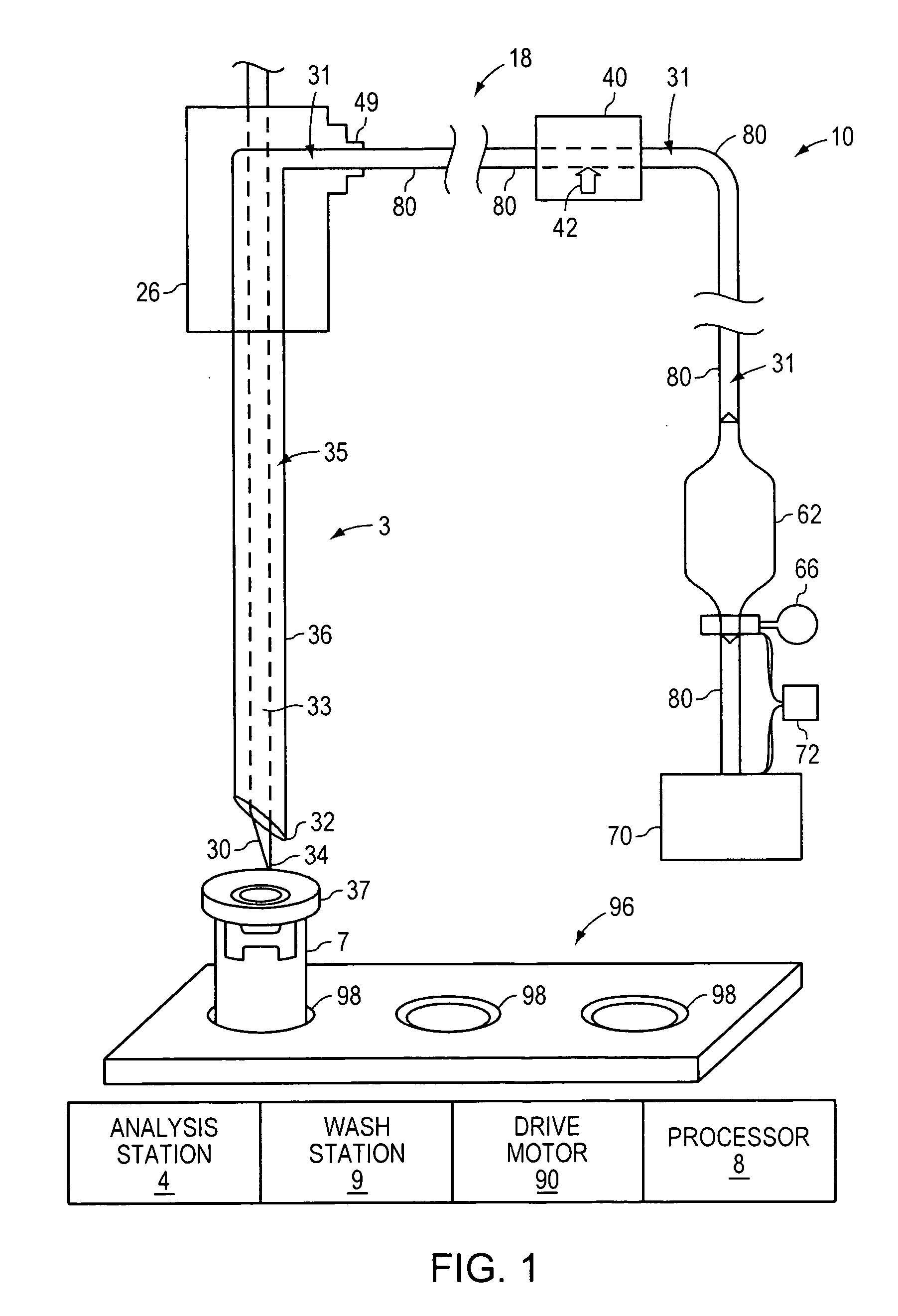
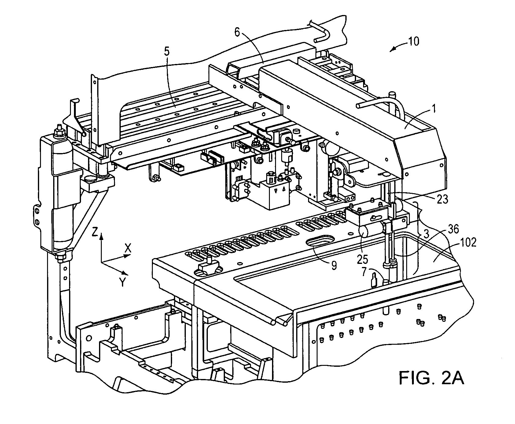
[0044] The present invention is related to a telescoping piercing probe and sample probe assembly and a venting mechanism mounted on a clinical diagnostic analyzer for automated piercing and sampling of fluid in a vial. The assembly includes a sample probe housed within a piercing probe. All of the following embodiments of the invention include features that improve the efficiency and effectiveness of an automated diagnostic sample analyzer including the piercing probe and sample probe assembly, and the venting mechanism of the invention.

[0045] Referring to FIG. 1, a sample collecting device 18, for example, a closed tube sample collecting device, is a component of an automated clinical diagnostic analyzer 10 that analyzes patient blood samples. The clinical diagnostic analyzer 10 may further include an analysis station 4, a wash station 9, a processor 8, a drive motor 90 and a sample tube rack 96. The sample tube rack 96 includes a plurality of sample tube wells 98. A patient bloo...


PUM


Abstract

A clinical diagnostic sample analyzer for analyzing a sample of a patient is disclosed. The analyzer includes a telescoping closed-tube sampling assembly with a sample probe concentrically housed within a piercing probe and a venting mechanism. The closed-tube sampling assembly is used for aspirating a sample from a sample tube for analysis by a clinical diagnostic sample analyzer.

Description

RELATED APPLICATIONS [0001] This application claims priority to and benefit of U.S. Provisional applications 60 / 678,615, filed on May 6, 2005 and 60 / 678,597 filed on May 6, 2005, the entirety of each application is incorporated by reference herein.FIELD OF THE INVENTION [0002] The invention relates to a clinical diagnostic analyzer for analyzing fluid samples such as patient blood samples. More particularly, the invention relates to a closed tube sample collecting device including a piercing probe and sample probe assembly mounted on a clinical diagnostic analyzer for accessing a fluid in vial, venting mechanisms associated with the closed tube sample collecting device, and methods for sampling and clearing a closed tube sample collecting device between patient samples to prevent cross contamination of the blood samples. BACKGROUND OF THE INVENTION [0003] Blood and other bodily fluids handled in large quantities by medical laboratories for processing and testing present cost contain...

Claims


Application Information

Patent Timeline
IPC IPC(8): G01N35/00
CPCB01L3/021B01L2300/0672B01L2400/0487G01N35/1004G01N35/1011Y10T436/2575B01L99/00G01N35/026G01N2035/1006Y10T436/114998G01N35/1079B01L13/02
Inventor BLOUIN, MATTHEWMURPHY, GREGORYMACKENZIE, DIANAWEEKS, ALANKOBRENSKI, DANIEL
Owner INSTR LAB
Learn More