Modular fuel stabilization system

a fuel stabilization system and module technology, applied in the direction of liquid degasification, membranes, separation processes, etc., can solve the problems of increasing the size of the fuel deoxygenator proportionally with the requirements, the required oxygen removal rate, and the inability of the single fuel deoxygenator to adapt to the variations in oxygen removal requirements. , to achieve the effect of optimizing the efficiency of dissolved oxygen removal

Active Publication Date: 2006-11-23
RTX CORP
View PDF52 Cites 15 Cited by
  • Summary
  • Abstract
  • Description
  • Claims
  • Application Information

AI Technical Summary

Benefits of technology

[0009] The modular approach to using a plurality of fuel deoxygenating devices instead of merely using one deoxygenating device provides many advantages. Those advantages include the ability to troubleshoot and replace a specific deoxygenator that may not be operating as desired. Further, the use of fuel deoxygenating devices in series or parallel allows for each device to be operated at different temperatures and thereby provide the hydrocarbon fuel with different usable cooling capacities that can be tailored to specific systems requirements. Finally, spreading the deoxygenation function among several independent fuel stabilization modules may also provide an advantage relative to overall system reliability and functionality, as the failure of one unit would not represent a complete loss of deoxygenation functionality but rather would only impact a portion of the overall system capability.
[0010] Accordingly, the fuel stabilization system according to this invention increases and optimizes the efficiency of dissolved oxygen removal from a fuel providing significant system benefits.

Problems solved by technology

Disadvantageously, the size of a fuel deoxygenator increases proportionably with the requirements for removing oxygen.
Further, as operational requirements change, so may the required oxygen removal rate.
A single fuel deoxygenator may not adjust readily or be scalable to accommodate variations in oxygen removal requirements.

Method used


Image

  • Modular fuel stabilization system
  • Modular fuel stabilization system
  • Modular fuel stabilization system

Examples


Embodiment Construction

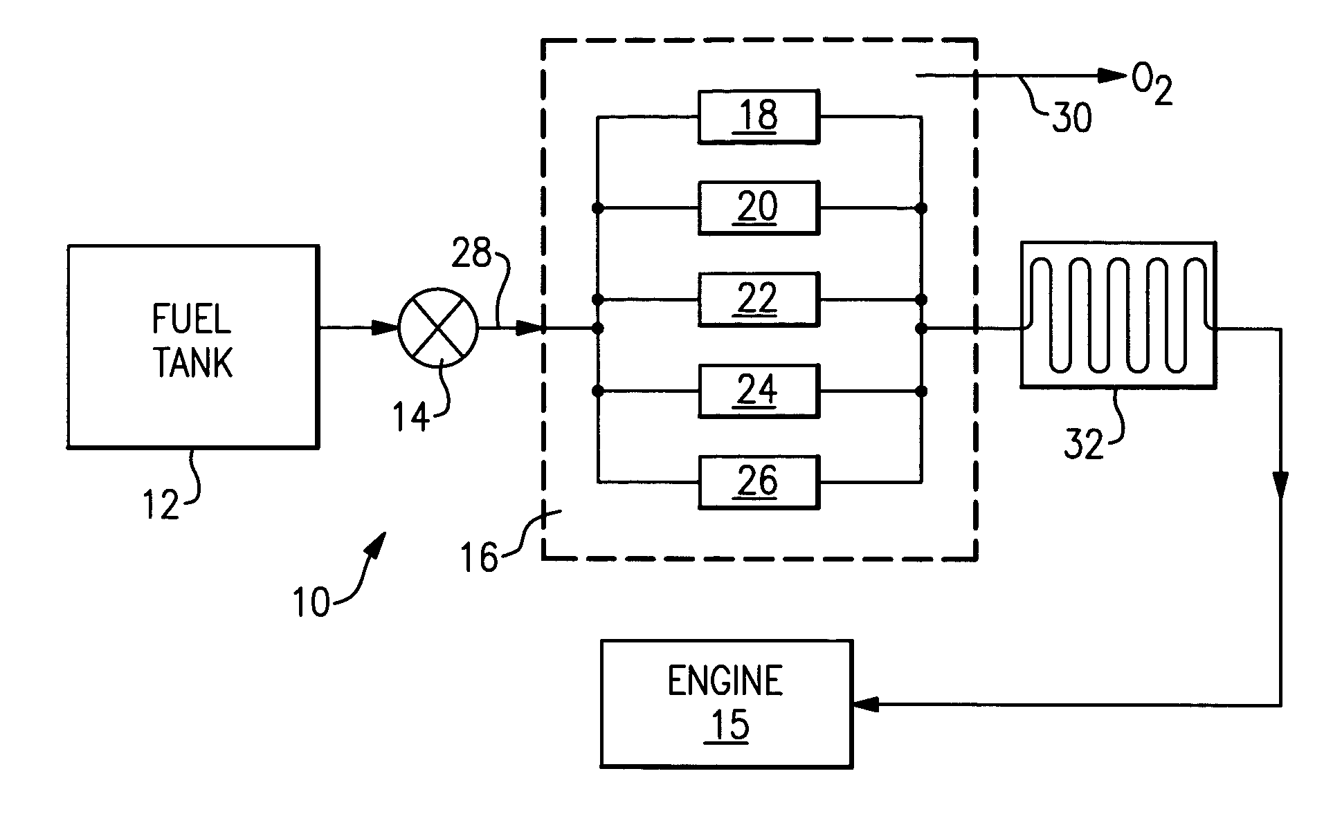
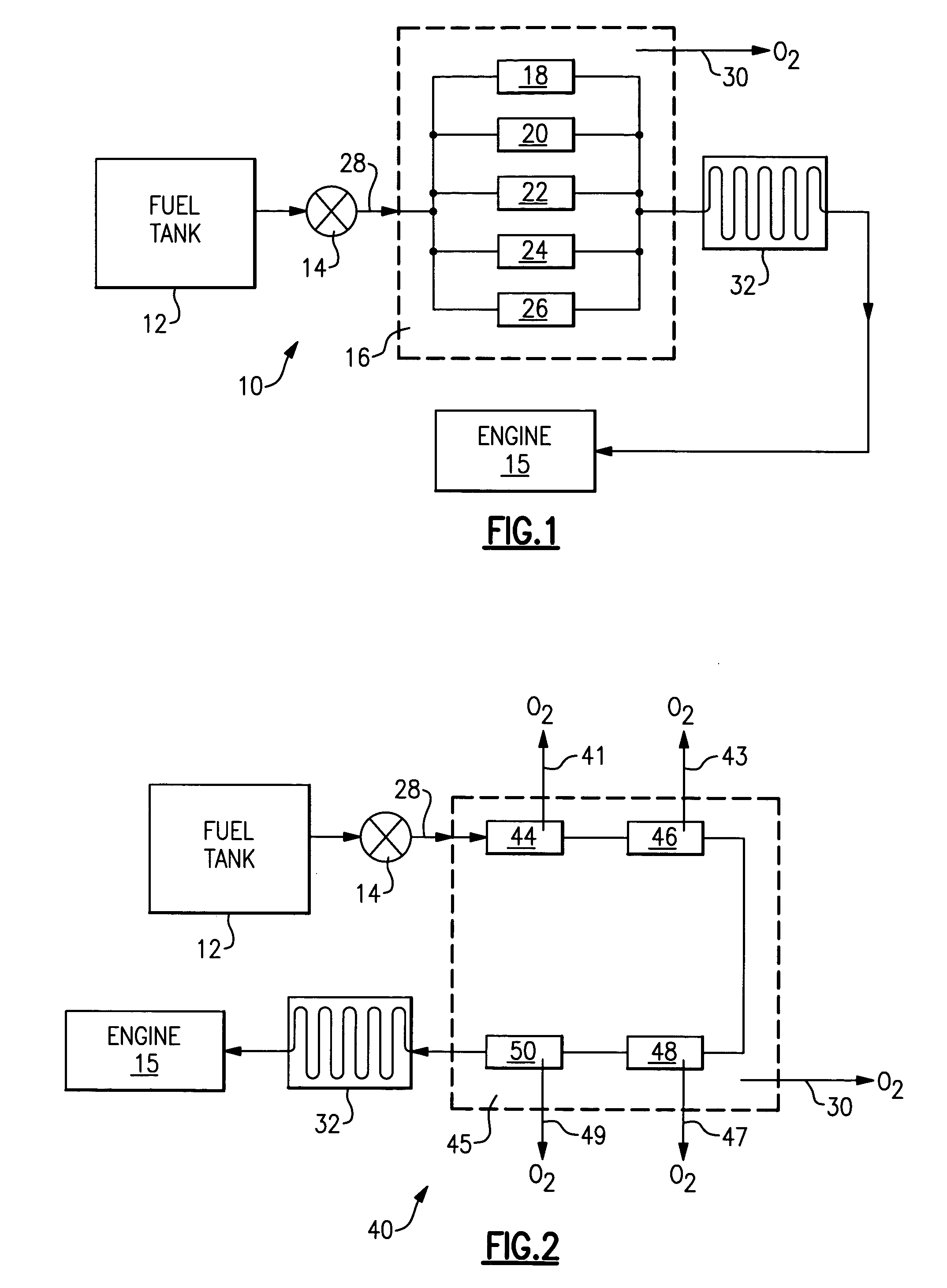
[0015] Referring to FIG. 1, a fuel stabilization system 10 is schematically illustrated and includes a fuel tank 12 or other fuel source that provides fuel by way of a fuel pump 14 to an engine 15. A fuel stabilization assembly 16 removes dissolved oxygen from within the fuel. The fuel stabilization assembly 16 includes a plurality of deoxygenators 18,20,22,24,26. The example fuel stabilization assembly 16 includes five deoxygenators 18, 20, 22, 24 and 26, arranged in a parallel configuration.

[0016] The parallel configuration provides a substantially uniform pressure drop across the fuel stabilization assembly 16. Each of the fuel deoxygenators 18, 20, 22, 24 and 26, provides an identical or very similar drop in fuel pressure. In some instances a single large deoxygenator can cause an undesirable drop in fuel pressure that is compensated for by other system devices such as the pump 14. However, the use of the plurality of parallel configured deoxygenators 18, 20, 22, 24 and 26 may ...


PUM

PropertyMeasurementUnit
inlet temperatureaaaaaaaaaa
temperaturesaaaaaaaaaa

Abstract

A fuel stabilization system includes a first deoxygenator and a second deoxygenator both for removing dissolved oxygen from a hydrocarbon fuel. The first and second deoxygenators are arranged in parallel or series to sequentially remove a portion of dissolved oxygen from the hydrocarbon fuel. The arrangement of several deoxygenators for a single fuel stream improves removal of dissolved oxygen and provides for scalability of the fuel system to meet application specific demands. The arrangement also provides for the preservation of partial system functionality in the event of the failure of one of the deoxygenator modules.

Description

BACKGROUND OF THE INVENTION [0001] This invention generally relates to a fuel stabilization system for an energy conversion device, and more particularly to a fuel stabilization system including several fuel deoxygenators for removing dissolved oxygen from a fuel. [0002] Hydrocarbon fuels typically include some amount of dissolved oxygen due to exposure to air during transport or storage. Dissolved oxygen within the fuel limits the temperature to which the fuel may be heated due to the formation of insoluble products referred to as “coke”. The formation of coke deposits is dependent on the amount of dissolved oxygen present within the fuel. Reducing the amount of dissolved oxygen within the fuel decreases the rate of coke deposition and increases the maximum sustainable temperature of the fuel. [0003] U.S. Pat. Nos. 6,315,815, and 6,709,432 assigned to Applicant, discloses devices for removing dissolved oxygen using a selective gas-permeable membrane disposed within the fuel system....

Claims


Application Information

Patent Timeline
Patent Type & Authority Applications(United States)
IPC IPC(8): B01J10/00B01J8/04
CPCB01D19/0031B01D19/0068B01D2317/022Y02T10/126F02M31/16F02M37/22F02M27/00Y02T10/12B01D19/00
Inventor TILLMAN, THOMAS GREGORYCHEN, ALEXANDER G.FOTACHE, CATALIN G.SPADACCINI, LOUIS J.LAMM, FOSTERMA, ZIDUCHIAPPETTA, LOUCOFFIN, CHARLES C.WILKINSON, JAMES A.WELCH, BRIAN
Owner RTX CORP
Why Eureka
Try Eureka