Method for determination of the supported position of a patient in a magnetic resonance apparatus

Inactive Publication Date: 2006-11-23
SIEMENS HEALTHCARE GMBH
View PDF14 Cites 11 Cited by
  • Summary
  • Abstract
  • Description
  • Claims
  • Application Information

AI Technical Summary

Benefits of technology

[0005] An object of the present invention is to provide a method and a magnetic resonance apparatus that allow an exact

Problems solved by technology

This can lead to severe consequences in later operations; for example, as has actually occurred, the right kidney being operated on instead of the left.
The subsequent correction of an

Method used


Image

  • Method for determination of the supported position of a patient in a magnetic resonance apparatus
  • Method for determination of the supported position of a patient in a magnetic resonance apparatus
  • Method for determination of the supported position of a patient in a magnetic resonance apparatus

Examples


Example

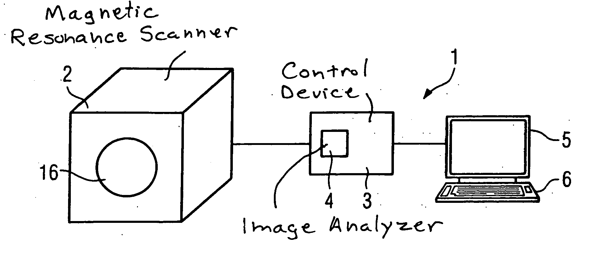
[0019]FIG. 1 shows an inventive magnetic resonance apparatus 1, having a magnetic resonance scanner 2 as well as an associated control device 3 which, in the shown example, includes an image analyzer 4. A monitor 5 for output of acquired images as well as an input unit 6 in the form of a keyboard are provided.

[0020] In known magnetic resonance apparatuses, the patient is typically arranged on a patient bed and inserted into the tube 16 of the scanner device 2 with a horizontal alignment of the patient bed. The shown example is a closed magnetic resonance device 2; but open devices are also known in which two device halves are arranged one atop the other and separated from one another, such that the patient can also be inserted from the side.

[0021]FIG. 2 shows the tube 16 as well as a coordinate system of the magnetic resonance scanner 2 using which the fixed (with regard to this device coordinate system) alignment of the coronal, sagittal and transversal localizer images is explai...


PUM


Abstract

In a method and magnetic resonance apparatus for determination of the position of the apparatus scanner, three localizer exposures situated orthogonally to one another are obtained during or after the insertion of the patient into the scanner. Using these three localizer exposures, an image analyzer automatically determines anatomical markers shown in the localizer exposures, which anatomical markers are dependent on the patient position in the scanner terms of their position in the localizer exposure. The spatial position of the patient is automatically determined by the image analyzer using the markers.

Description

BACKGROUND OF THE INVENTION [0001] 1. Field of the Invention [0002] The invention concerns a method for determination of the supported position of a patient in a magnetic resonance apparatus, as well as a magnetic resonance apparatus operating according to the method. [0003] 2. Description of the Prior Art [0004] In the examination of a patient in a magnetic resonance apparatus, the patient can be supported in eight different positions. The patient can be positioned head-first or the feet-first, lying on his or her back or his or her stomach, or lying on the left side or on the right side. The detection of how the patient is currently positioned, consequently how the patient is thus arranged with regard to the coordinate system of the magnetic resonance apparatus conventionally ensues by an operating person that inputs the patient positioning into the apparatus computer at the beginning of the registration procedure. The input of the (expected or intended) patient position typically...

Claims


Application Information

Patent Timeline
IPC IPC(8): A61B5/05
CPCA61B5/0555A61B19/5244A61B2019/5289A61B2019/5265A61B2019/5287A61B2019/5236A61B5/055A61B34/20A61B2034/2065A61B2090/363A61B2090/364A61B2090/374
Inventor FABER, ROLANDSCHRECK, OLIVER
Owner SIEMENS HEALTHCARE GMBH
Why Eureka
Try Eureka