Self powered osteogenesis and osseointegration promotion and maintenance device for endosseous implants

a technology of osteogenesis and osseointegration, which is applied in the field of self-powered devices, can solve the problems of low bone-to-implant contact ratio, poor bone strength at the interface, and the risk of crestal bone loss of the implantant,

Inactive Publication Date: 2006-11-23
CELLECTRIC MEDICAL
View PDF26 Cites 43 Cited by
  • Summary
  • Abstract
  • Description
  • Claims
  • Application Information

AI Technical Summary

Problems solved by technology

However, the implant is still at a risk of failure and crestal bone loss within the first year, some of the main reasons being poor bone strength at the interface, and low bone-to-implant contact ratio.
This type of bone is only partly mineralized, and therefore less able to withstand the high magnitude forces applied on the implant.
This delay is a clear disadvantage of the conventional procedure in use today, leaving the patients with impaired oral function and esthetics because of the missing teeth.
Crack fatigue in the cement layer and osteolysis can lead to prosthesis loosening and eventual failure.
However, the art that relates specifically to dental bone growth stimulation by small, self powered electrical means is very limited.
While Nickerson does not provide details of the battery, it is clear from his description that his battery is volumetrically extremely small, thus having very small capacity, which may not suffice for effective DC stimulation.
Moreover, DC stimulation is known to have negative side effects.
For example, Kronberg in U.S. Pat. No. 6,321,119 points out that studies on electrical stimulation of bone growth have shown that application of DC stimuli alone may be problematic in stimulating bone regeneration since bone grows near the cathode (i.e. the negative electrode), but often dies away near the anode.
This phenomenon may result from electrolytic effects, which can cause tissue damage or cell death through pH changes or the dissolution of toxic metals into body fluids.
Other disadvantages of Nickerson's device include: being sunken into the gingiva, it has an internal volume too small to contain a large enough battery.
Its shape causes great discomfort upon removal.
Its insulation section is larger than the battery itself, limiting the size of the battery even more.
Although bone growth stimulation by AC or pulsed currents is deemed beneficial, there are no known practical, self-powered, compact dental stimulator caps using such currents.
Sawyer's disclosure mentions an embodiment of a bionic tooth powered by a battery and including an AC circuit that is clearly impractical: among major disadvantages, it does not appear to be removable without major surgery (since removal of his upper portion 26 occurs by unscrewing insulating member 30 from external implant thread 22, thus causing major trauma to the extensive gingival area contacted by portion 26); it uses a preferred signal frequency range of 0.5 to 1 mHz; and it cannot provide current pulses.
Its battery cap (“crown”) is too long, penetrating deep into the gingiva (or even through the bone), thus being unfeasible and useless from a surgeon's point of view.
Also, Sawyer's device is not a dual-function device, i.e. it does not serve as a temporary abutment on which one can install a temporary crown.
However, Dugot's system is not a compact, self-powered stimulator cap, but a cumbersome, externally (to the implant) wired and powered stimulator, which does not appear to be feasibly applicable to human dental implants.
However, Michelson's apparatus is not an adaptation of a readily available implant, nor does it have an optimal configuration of electrodes.
None of these devices perform satisfactory osteogenesis promotion, maintenance or acceleration while leaving the implant member or stem essentially unchanged in appearance and mechanical properties.

Method used


Image

  • Self powered osteogenesis and osseointegration promotion and maintenance device for endosseous implants
  • Self powered osteogenesis and osseointegration promotion and maintenance device for endosseous implants
  • Self powered osteogenesis and osseointegration promotion and maintenance device for endosseous implants

Examples


Embodiment Construction

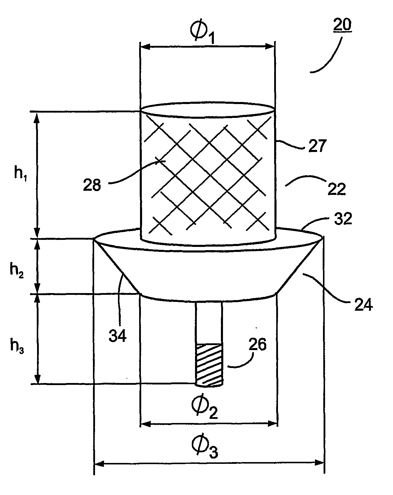
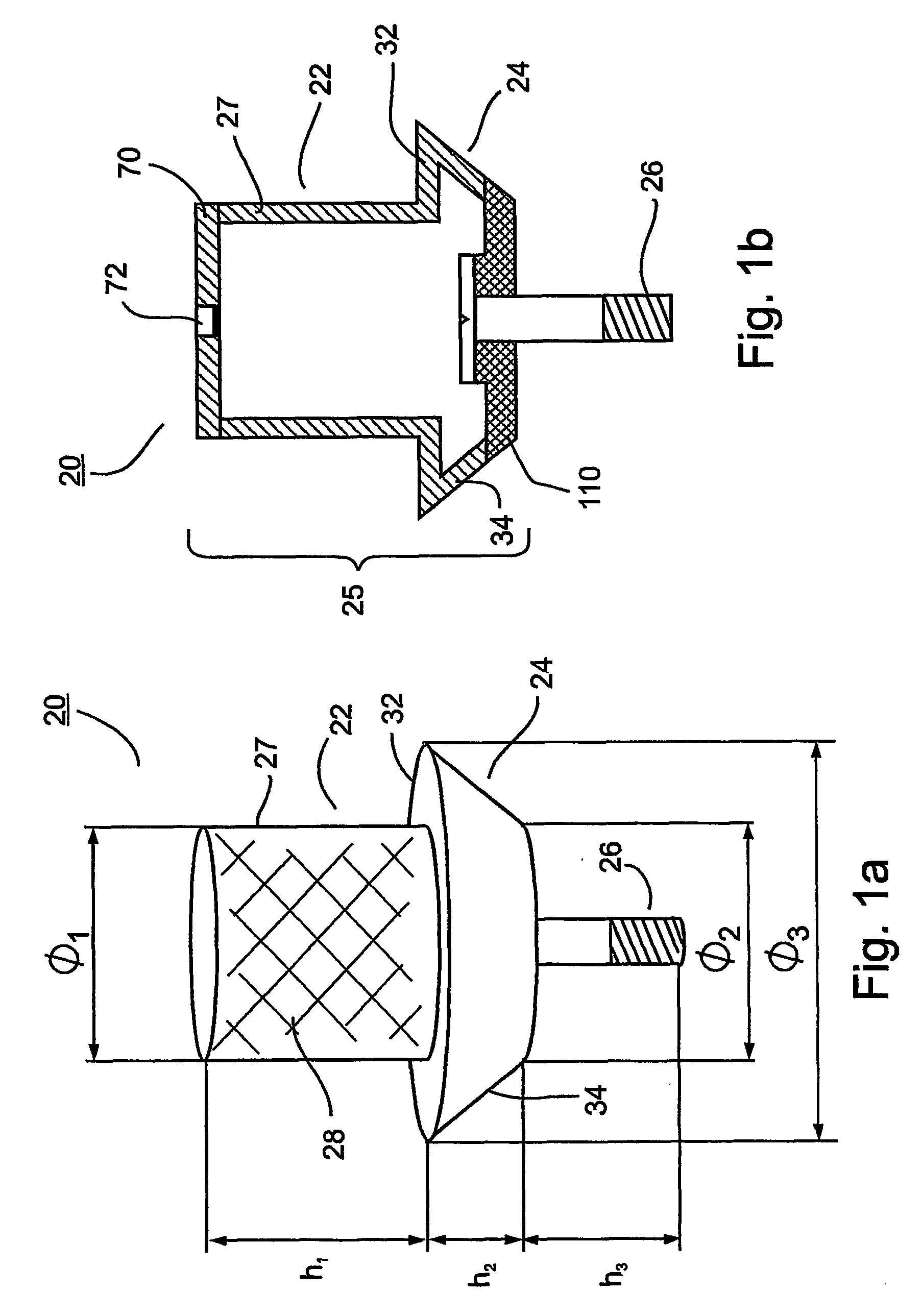
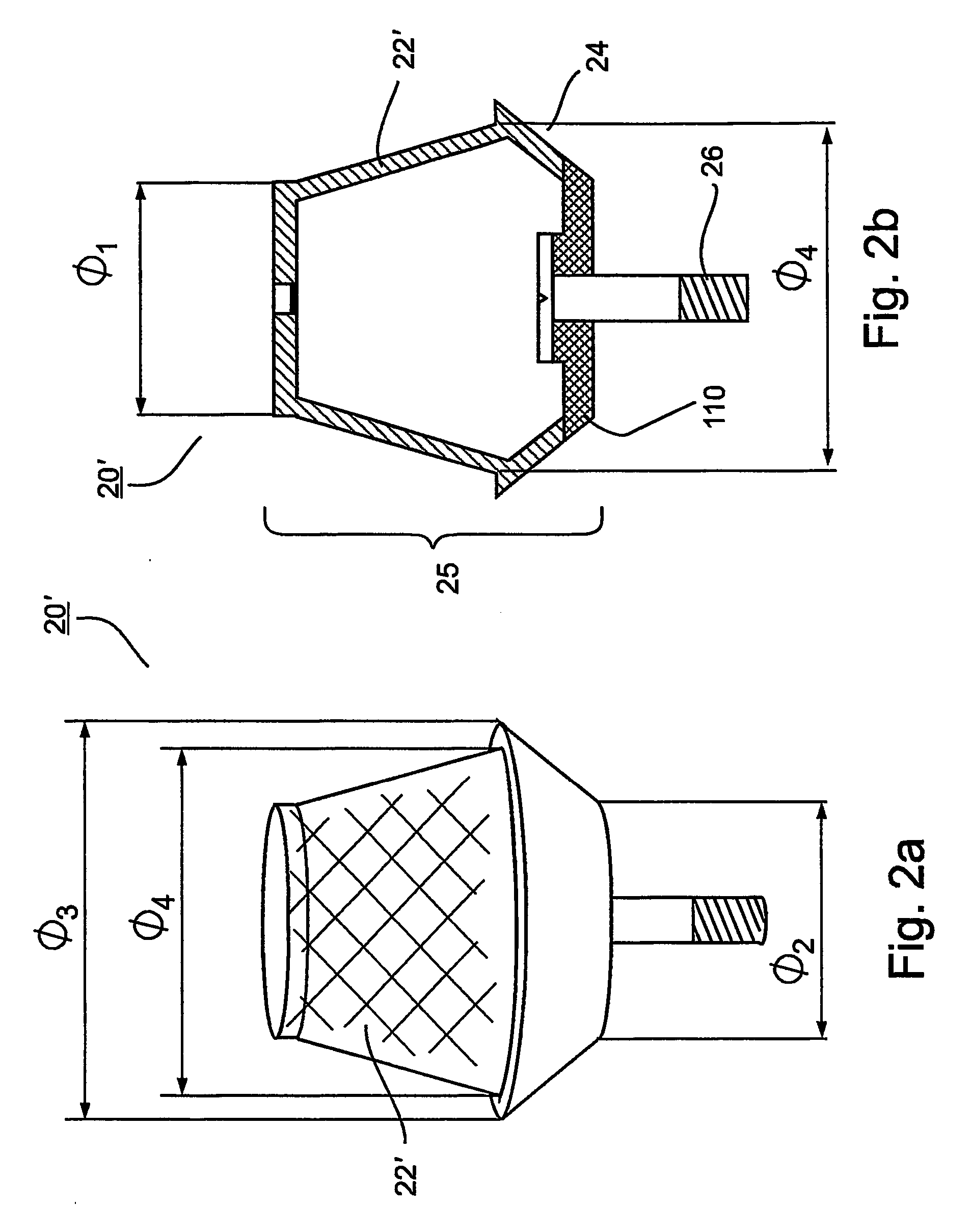
[0046] The present invention discloses, in various embodiments, an osteogenesis and osseointegration promotion and maintenance device (hereinafter “osteogenesis device”) for endosseous implants, capable of providing DC, AC and arbitrary current train pulses, or any combination thereof. In a preferred embodiment in which the osteogenesis device is self-powered, the device preferably uses as power source an internal battery that may be miniaturized (i.e. a microbattery). The microbattery may be further integrated with electronic and / or actuating circuitry. Alternatively, the osteogenesis device can be powered remotely from outside the body. In embodiments of devices with extremely small internal cavity volumes (such as a dental implant) that cannot use conventional batteries, the internal battery is preferably a three-dimensional (3D) thin film micro-electro-chemical cell as described in U.S. Pat. No. 6,197,450 to Nathan et. al. The micro-electro-chemical cell may be integrated on the...


PUM

PropertyMeasurementUnit
voltagesaaaaaaaaaa
voltagesaaaaaaaaaa
frequencyaaaaaaaaaa

Abstract

Osteogenesis and osseointegration promotion and maintenance devices for osseous implants include an implant member having a first electrode, an inlaid second electrode positioned on the member so that it is electrically isolated from and substantially flush with the member surface, and an electrical stimulation mechanism preferably located at the member and operative to provide electrical stimulation signals to endosseous tissue surrounding the implant through the first and second electrodes. The first electrode may be the member itself or a second inlaid electrode. The implant is thus electrically functionalized for osteogenesis and osseointgration acceleration. The device is applicable to both non-dental and dental implants. In all embodiments, the use of inlaid electrode(s) enables the general appearance, external surface and mechanical integrity of the implant to be left essentially unchanged.

Description

FIELD AND BACKGROUND OF THE INVENTION [0001] The present invention relates to processes of accelerating bone growth (osteogenesis) and bone tissue healing around endosseous implants. In particular, the present invention relates to self-powered devices incorporated in, or attached to a surgically inserted implant, for example a dental implant or a hip or knee implant, or devices having an external power source, the devices used for accelerating bone growth and healing in and around the implant surgical site. By “self-powered” we mean devices that include a built-in power source such as a battery. The following description deals in detail with both dental and orthopedic (non-dental) implants, e.g. hip implants, knee implants, etc. [0002] A major concern for all implants, and in particular non-dental implants such as hip or knee implants, is that external appearance, feel, and mechanical integrity and function remain essentially unchanged. Moreover, a surgeon implanting for example a h...

Claims


Application Information

Patent Timeline
Patent Type & Authority Applications(United States)
IPC IPC(8): A61N1/00A61C8/00A61F2/00A61F2/28A61F2/30A61F2/36A61N1/32
CPCA61C8/0006A61N1/326A61C8/005A61C8/0068A61C8/0069A61F2/30767A61F2/36A61F2/3662A61F2/3676A61F2002/2821A61F2002/30289A61F2002/3082A61F2002/30822A61F2002/30827A61F2002/30981A61F2002/3611A61F2002/3692A61F2230/0091A61F2310/00023A61F2310/00149A61F2310/00155A61F2310/00616A61C8/0007A61F2/3094A61F2002/30593
Inventor MADJAR, DAVIDNATHAN, MENACHEMPELED, EMANUELTERKEL, HANAN
Owner CELLECTRIC MEDICAL
Why Eureka
Try Eureka