Liquid measurement system having a plurality of differential pressure probes

a liquid measurement system and differential pressure technology, applied in liquid/fluent solid measurement, instruments, machines/engines, etc., can solve the problems of difficult accuracy of capacitance measurement of such a small amount, high cost of capacitive fuel probes, and inability to accurately determine liquid weight, etc., to achieve accurate determination of liquid weight, less cost, and high accuracy

Inactive Publication Date: 2006-11-30
BAE SYSTEMS CONTROLS INC
View PDF15 Cites 20 Cited by
  • Summary
  • Abstract
  • Description
  • Claims
  • Application Information

AI Technical Summary

Benefits of technology

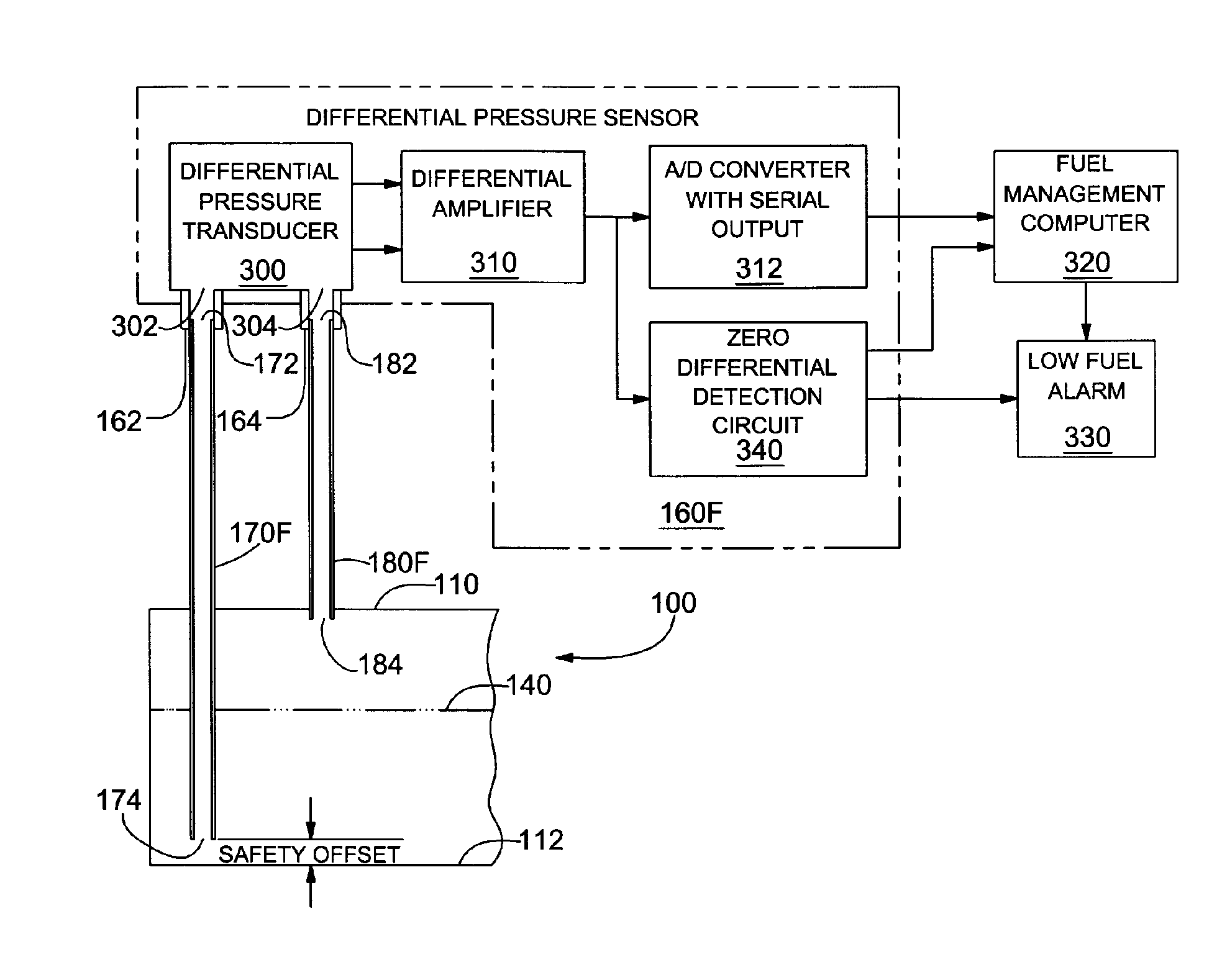
[0005] The weight of liquid in a tank that is subject to tilting is determined by measuring differences between the air pressure in the ullage (the empty volume of the tank above the level of the liquid) and the air pressure produced by the weight of the liquid at the bottom of the tank. The pressures at the bottom of the tank are measured in a plurality of locations using differential pressure transducers, and the differential pressures are used to determine the quantity of liquid remaining in the tank. The system determines the liquid quantity even when the tank is tilted. For example, the quantity of liquid remaining in a tank of an aircraft is determined when the aircraft is at an attitude other than straight and level flying. The electronics to measure the pressure and to process the pressure measurements are located remotely from the tank, thus eliminating the possibility of ignition caused by the electronics when the liquid is aviation fuel or another flammable material.
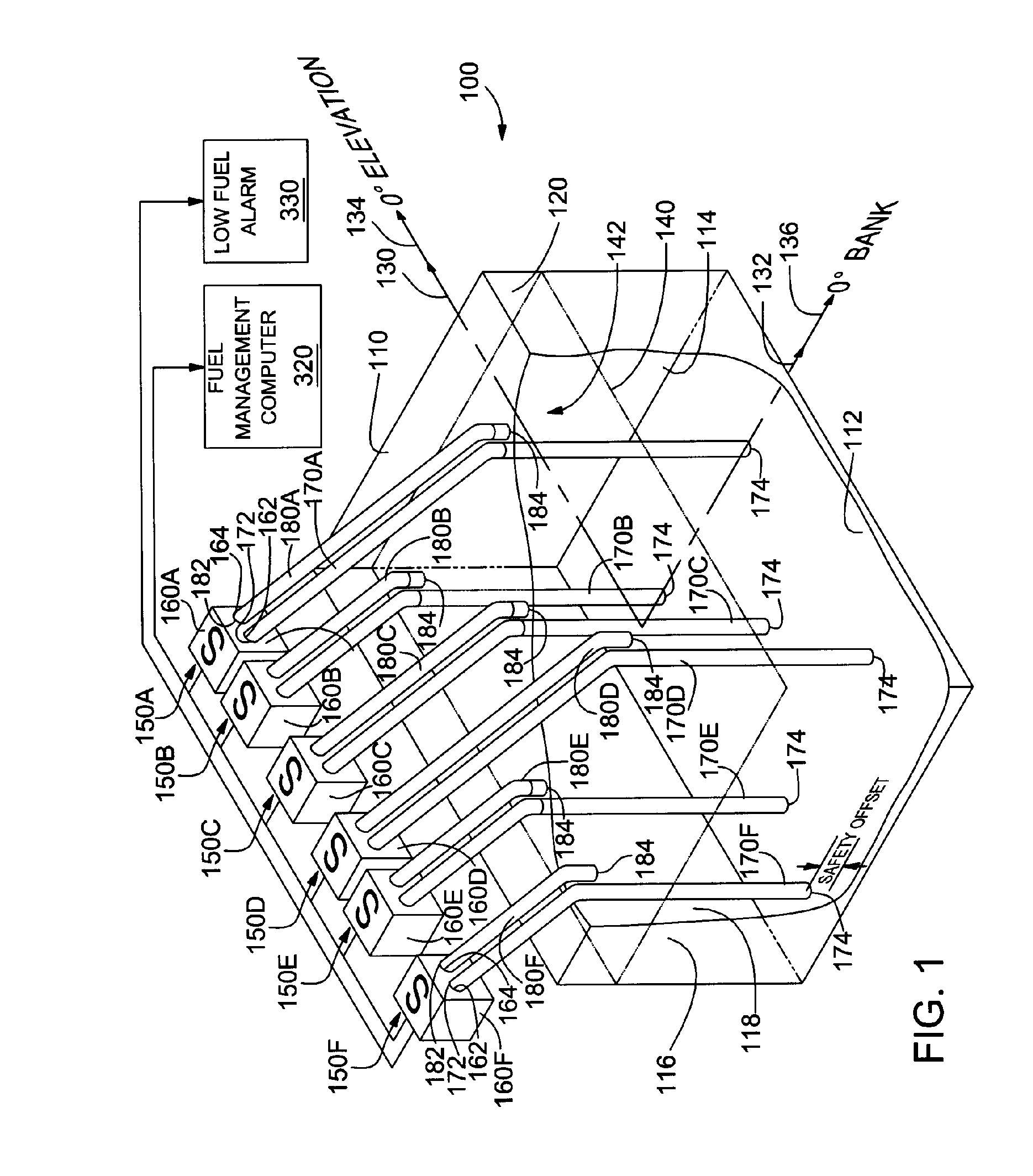
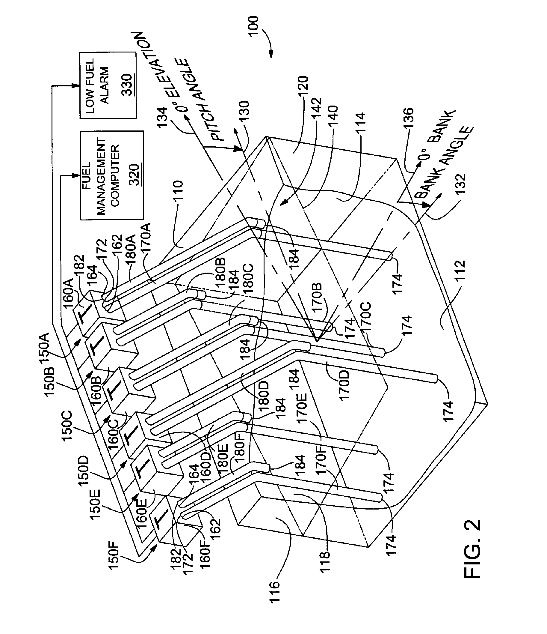
[0008] A plurality of measurement probes are located in each tank to compensate for changes in the attitude (e.g., tilting) of the tank. For example, the tank may be tilted by movement of the aircraft (e.g., changes in elevation (pitch), bank and yaw) or by being positioned on an uneven support structure or surface. The pressure measurements from the multiple probes in each tank are combined to account for the tilting of the tank issue to eliminate the need to independently measure the tilt angle of the tank.
[0010] The differential pressure probes described herein are less costly than capacitive measurement probes. Furthermore, no electronics are located in the tanks. The system uses pressure sensors which are highly accurate. The combination of the accurate pressure sensors and averaging of the differential measurements from the plurality of probes enables the system to accurately determine the liquid weight. The measurement probes are lightweight and are constructed of materials that will not damage the tanks in the event of a crash or a hard landing. The differential probes are easily configured for different tank sizes and shapes. The differential probes work with all liquid types and do not require temperature compensation. The multiple probes enable compensation for the tilt angle of the tank. The probes are simple to install and easy to maintain and repair. Since no wiring in the tanks is required, the probes are immune to lightning and electromagnetic interference (EMI) and are thus particularly suitable for use in tanks containing fuel or other flammable materials.

Problems solved by technology

Therefore, an accurate measurement of such a small capacitance is challenging, especially, since the stray wiring capacitance can far exceed 100 picofarads.
Thus, capacitive fuel probes are very expensive and may cost in a range of $600-$2,000 per probe.
Since the capacitive probes are operated electronically, a portion of the electronics are typically located in the fuel tanks, which may present a risk of explosion.

Method used


Image

  • Liquid measurement system having a plurality of differential pressure probes
  • Liquid measurement system having a plurality of differential pressure probes
  • Liquid measurement system having a plurality of differential pressure probes

Examples


Embodiment Construction

[0017]FIG. 1 illustrates a tank 100 that may be used for transporting liquid in an aircraft or other machinery subject to movement. For example, the tank 100 may be a fuel tank located within the fuselage or a wing of an aircraft or it may be located within a ground transportation vehicle. In the following description, the tank 100 is located in an aircraft (not shown). Although described herein with respect to the fuel tanks of an aircraft, the invention may advantageously be embodied in other systems for measuring fuel in environments where the tank containing the fuel is subject to tilting. The invention may also be embodied in systems for measuring other liquids, such as, for example, the fire suppression liquids (e.g., water) carried in tanks of firefighting equipment.

[0018] The tank 100 may have many different configurations in order to conform the tank to the structure of the aircraft or other environment in which the tank is located. For example, the tank 100 may have an ir...


PUM


Abstract

The weight of liquid in a tank subject to tilting is determined by measuring differences in air pressure in the ullage (the empty volume of the tank above the level of the liquid) and the air pressure produced by the weight of the liquid at the bottom of the tank. The pressures at the bottom of the tank are measured in a plurality of locations, and the differential pressures are combined to compensate for changes in the depth of the liquid when the tank is not level (e.g., when the tank is in an aircraft flying at an attitude other than straight and level). The electronics to measure the pressure and to process the pressure measurements are located remotely form the tanks, thus eliminating the possibility of ignition caused by the electronics when the liquid is fuel or other flammable liquid.

Description

BACKGROUND OF THE INVENTION [0001] 1. Field of the Invention [0002] The present invention is related to the measurement of liquid in a tank that is subject to tilting, and, more particularly, is related to the measurement of the weight of the liquid in the tank by determining differences in pressures at multiple locations in the tank. [0003] 2. Description of the Related Art [0004] The measurement of the fuel remaining in the fuel tanks of an aircraft is highly important in order to assure that an aircraft is not flown beyond the limits of the available fuel. Fuel measurement techniques have evolved from the original method of inserting a rod into the tank prior to a flight. A current industry standard for measuring fuel uses capacitive probes, which measure the height of the fuel in a tank by measuring the change in capacitance of concentric tubes. The principle behind this approach is that changing fuel levels change the dielectric constant between the concentric tubes. In particu...

Claims


Application Information

Patent Timeline
Patent Type & Authority Applications(United States)
IPC IPC(8): G01F23/00
CPCG01F23/162G01F23/14G01F23/18G01F23/802
Inventor GOURLAY, ROBERT D.WILLIAMS, STEVEN C.PAGAN, DANIEL L.
Owner BAE SYSTEMS CONTROLS INC
Why Eureka
Try Eureka