Cleaning sheet and cleaning method using same

a technology of cleaning sheet and cleaning method, which is applied in the field of sheets, can solve the problems that the top of the division wall cannot provide an accurate display, and the back paste attached to the division wall cannot prevent the accurate and beautiful arrangement of fluorescent materials, and achieves the effect of simple structure and preferable cleaning

Inactive Publication Date: 2006-11-30
NITTO DENKO CORP
View PDF4 Cites 15 Cited by
  • Summary
  • Abstract
  • Description
  • Claims
  • Application Information

AI Technical Summary

Benefits of technology

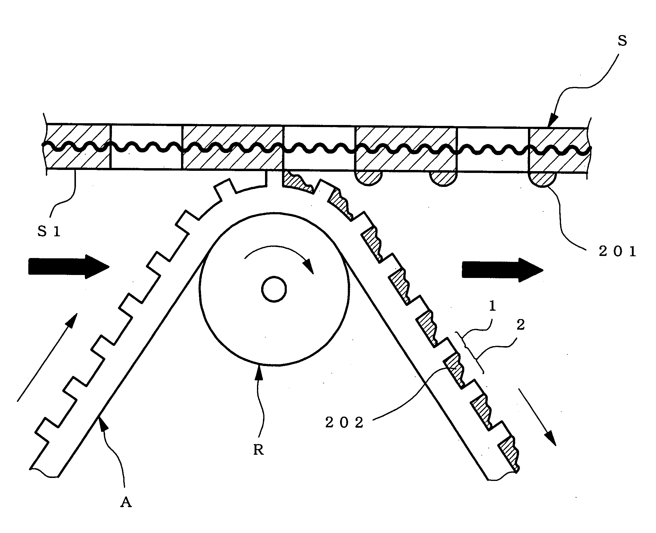
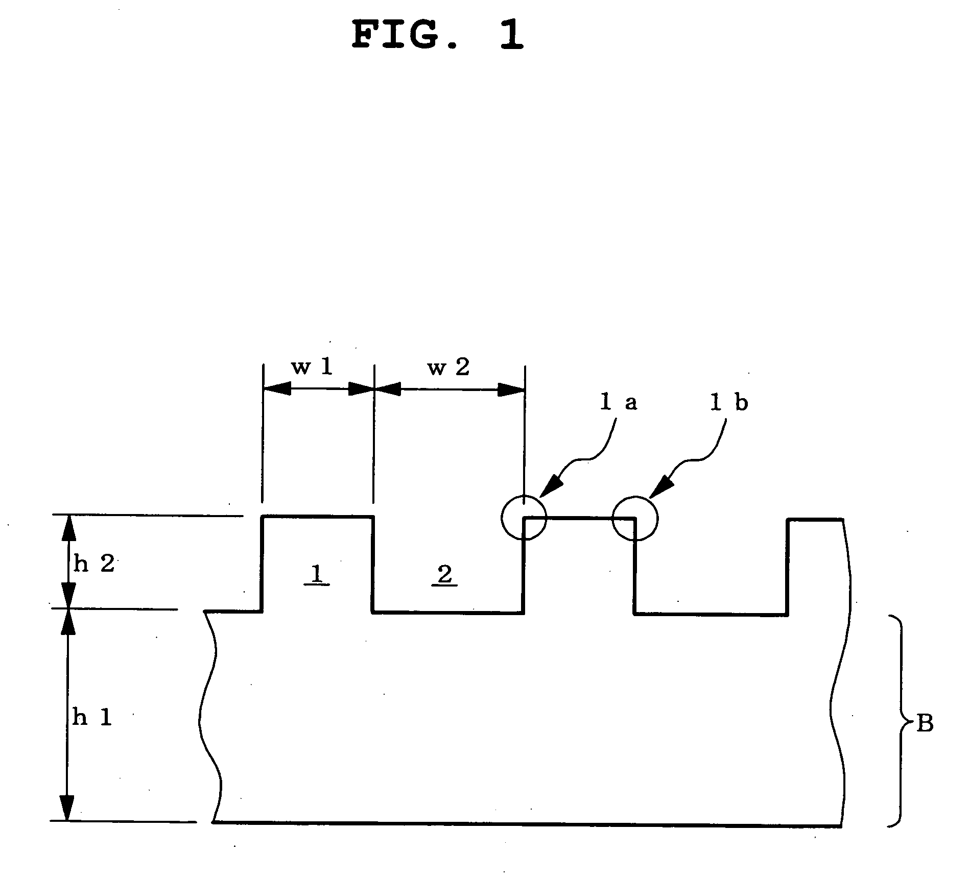
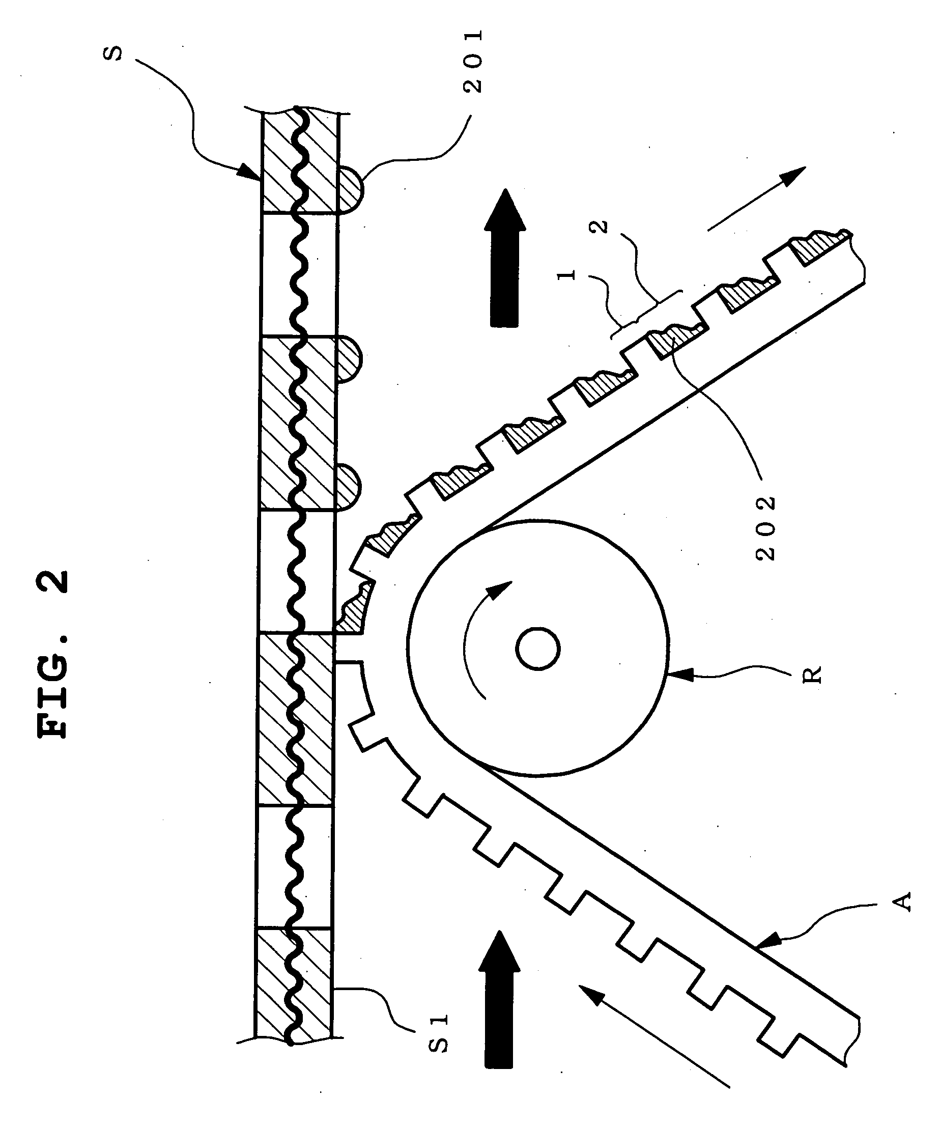
[0013] The present inventors have conducted intensive studies in an attempt to achieve the above-mentioned object, and found that the back paste alone can be scraped off by processing the contact face of a sheet into a concave convex shape and rubbing the convex face against a cleaning object like a wiper, by which the back paste thus scraped off remains in the concave part. Thus, they have found that such a simple structure enables preferable cleaning, which resulted in the completion of the present invention.

Problems solved by technology

When adjacent fluorescent materials are mixed even topically, the mixed part alone cannot provide an accurate display.
The residue (back paste) that attached to the top of division walls prevents accurate and beautiful arrangement of the fluorescent materials.

Method used


Image

  • Cleaning sheet and cleaning method using same
  • Cleaning sheet and cleaning method using same
  • Cleaning sheet and cleaning method using same

Examples


example 1

[0116] In this Example, Example products having a concave convex pattern of a contact face with a cross sectional shape shown in FIG. 7(b), and having various values of width w1 of convex part, width w2 of concave part, thickness h1 of base sheet and height of the convex part h2 were produced, and the removal performance of the removal target and consumed amount of the sheet necessary for the removal of each product were evaluated.

[0117] As a Comparative Example product for comparison with the Example products, a conventional adhesive cleaning sheet (adhesive sheet) free of concave convex on a contact face was prepared, and the removal performance of the removal target, and the consumed amount of the sheet necessary for the removal were evaluated.

[Production of Example products]

[0118] A polyethylene resin having a density of 0.92 g / cm3, was extrusion molded from a T-type die at 190° C. to give a 150 μm-thick molten sheet, which was pressed with a concave convex squeezing roller a...

example 2

[0129] While a PET film was used as a cleaning object in the above-mentioned Example 1 to examine a preferable embodiment of the cleaning sheet, an actual screen printing plate was used as a cleaning object in this Example. The screen printing plate is a member for forming a fluorescent material layer of PDP as shown in FIG. 13(a), which was diverted for use in the experiment.

[0130] Moreover, to reproduce the state of use of the cleaning sheet in the actual screen printing apparatus as accurately as possible, a cleaning test apparatus shown in FIG. 13(b) was manufactured.

[0131] In the actual screen printing apparatus, a cleaning apparatus set back at the side moves to the plate surface area and automatically wipes off a back paste during the interval of screen printing. The cleaning test apparatus as shown in FIG. 13(b) is able to change pressurization conditions, reeling speed of the sheet, whole advance speed and the like while reproducing the cleaning movement in an actual mach...


PUM

PropertyMeasurementUnit
boiling pointaaaaaaaaaa
angleaaaaaaaaaa

Abstract

According to the present invention, of the both surfaces of a cleaning sheet, a contact face to be rubbed against a cleaning object is a concave convex plane containing a convex part 1 and a concave part 2. By rubbing this concave convex plane against a cleaning object, a removal target (e.g., paste accumulated on the back of screen printing plate) attached to a cleaning object can be effectively removed.

Description

FIELD OF THE INVENTION [0001] The present invention relates to a sheet for cleaning an object to be cleaned (hereinafter a cleaning object) by removing an object to be removed (hereinafter a removal target) attached thereto, such as paste, ink and the like. More particularly, the present invention relates to a cleaning sheet for wiping off a fluorescent material paste spread on the back of the mating face of a screen printing plate, during production and the like of a fluorescent material layer incorporated in a plasma display panel (PDP), and a cleaning method using the sheet. BACKGROUND OF THE INVENTION [0002] In recent years, PDP (particularly, color PDP) is becoming bigger and more highly defined, and the arrangement pattern of an RGB fluorescent material in its fluorescent material layer is becoming ultrafine and highly dense. [0003] In a step for forming a fluorescent material layer, as shown in FIG. 14(a) with a schematic sectional view, each fluorescent material for the thre...

Claims


Application Information

Patent Timeline
Patent Type & Authority Applications(United States)
IPC IPC(8): B08B7/00B32B3/00B08B1/00B41F15/12B41F35/00
CPCY10T428/24479B41F35/005H01J9/38B41F31/20H01J11/20
Inventor YAMANAKA, EIJIYONEDA, MASANOBUYATAGAI, TAKAHIRODEGAWA, OSAMU
Owner NITTO DENKO CORP
Why Eureka
Try Eureka