Zoom optical system and image pickup apparatus

a technology of optical system and image pickup, which is applied in the direction of optics, instruments, lenses, etc., can solve the problems of difficult to utilize the third lens group so as to adequately correct aberration, and difficult to make a shortest object distance at a telephoto point. , to achieve the effect of adequately shortest focal length, reducing distance, and increasing distan

Inactive Publication Date: 2006-11-30
KONICA MINOLTA PHOTO IMAGING
View PDF14 Cites 18 Cited by
  • Summary
  • Abstract
  • Description
  • Claims
  • Application Information

AI Technical Summary

Benefits of technology

[0013] A zoom optical system for forming an optical image of an object on an image-sensing surface of an image pickup element, said zoom optical system comprises, in order from an object side thereof: a first lens group having a negative refractive power; a second lens group having a positive refractive power; a third lens group having a negative refractive power; and a fourth lens group having a positive refractive power. The zoom optical system moves at least the second lens group and the third lens group for zooming operation from a wide-angle end to a telephoto end so as to reduce a distance between the first lens group and the second lens group and increase a distance between the third lens group and the fourth lens group. The zoom optical system also moves the third lens group for a focusing operation. The first lens group comprises, in order from the object side of the zoom optical system, a meniscus lens having a negative refractive power whose concave surface faces an image side of the zoom optical system, a reflective optical element, and at least one lens.
[0014] It becomes possible to structure an image pickup apparatus having a compact and high performance zoom optical system and an image pickup apparatus having the same while maintaining an adequately shortest focal length by applying the structure of the present invention.

Problems solved by technology

Consequently, there is a problem that it is difficult to make a shortest object distance at a telephoto point in which a moving distance is particularly long.
In this case, since the third lens group approaches to the image surface side, it becomes difficult to utilize the third lens group so as to adequately correct aberration.
Further, there is a problem that the size of the total lens system becomes large when securing the adequate distance between the third lens group and the image surface in order to avoid the problem described above.
However, there is a problem that since the concave surface of the first surface of the lens located in the most object side is arranged to face to the object side, off-axis aberration occurs and many aspherical surfaces are required to correct the off-axis aberration.
Further there is a problem that the total length of the lens has to be prolonged.
There are problems that in order to correct the off-axis aberration, many aspherical surfaces are required and the total length of the lens has to be prolonged.

Method used


Image

  • Zoom optical system and image pickup apparatus
  • Zoom optical system and image pickup apparatus
  • Zoom optical system and image pickup apparatus

Examples


example

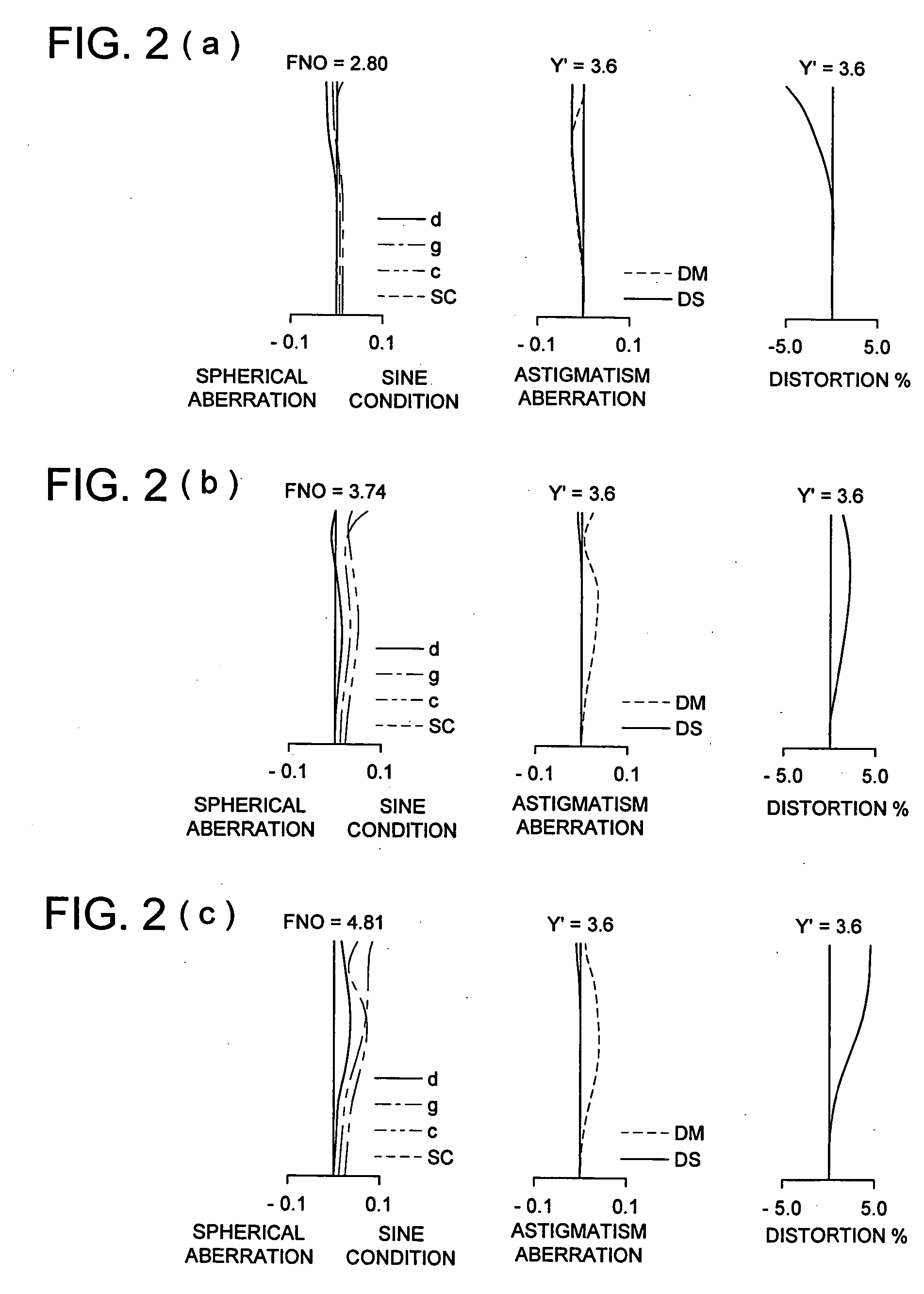
[0065] The configuration of a zoom optical system installed into the image pickup apparatus of the embodiment according to the present invention will be concretely described by using construction data and aberration diagrams.

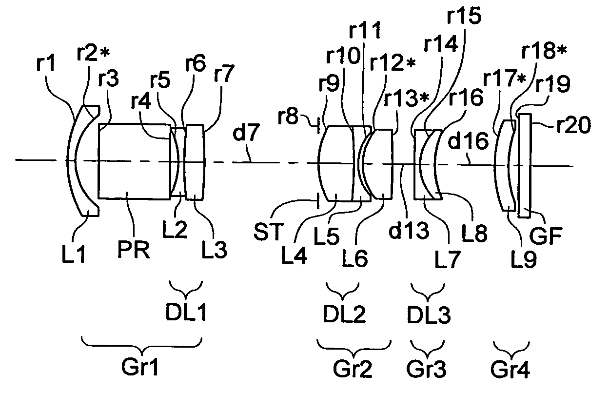
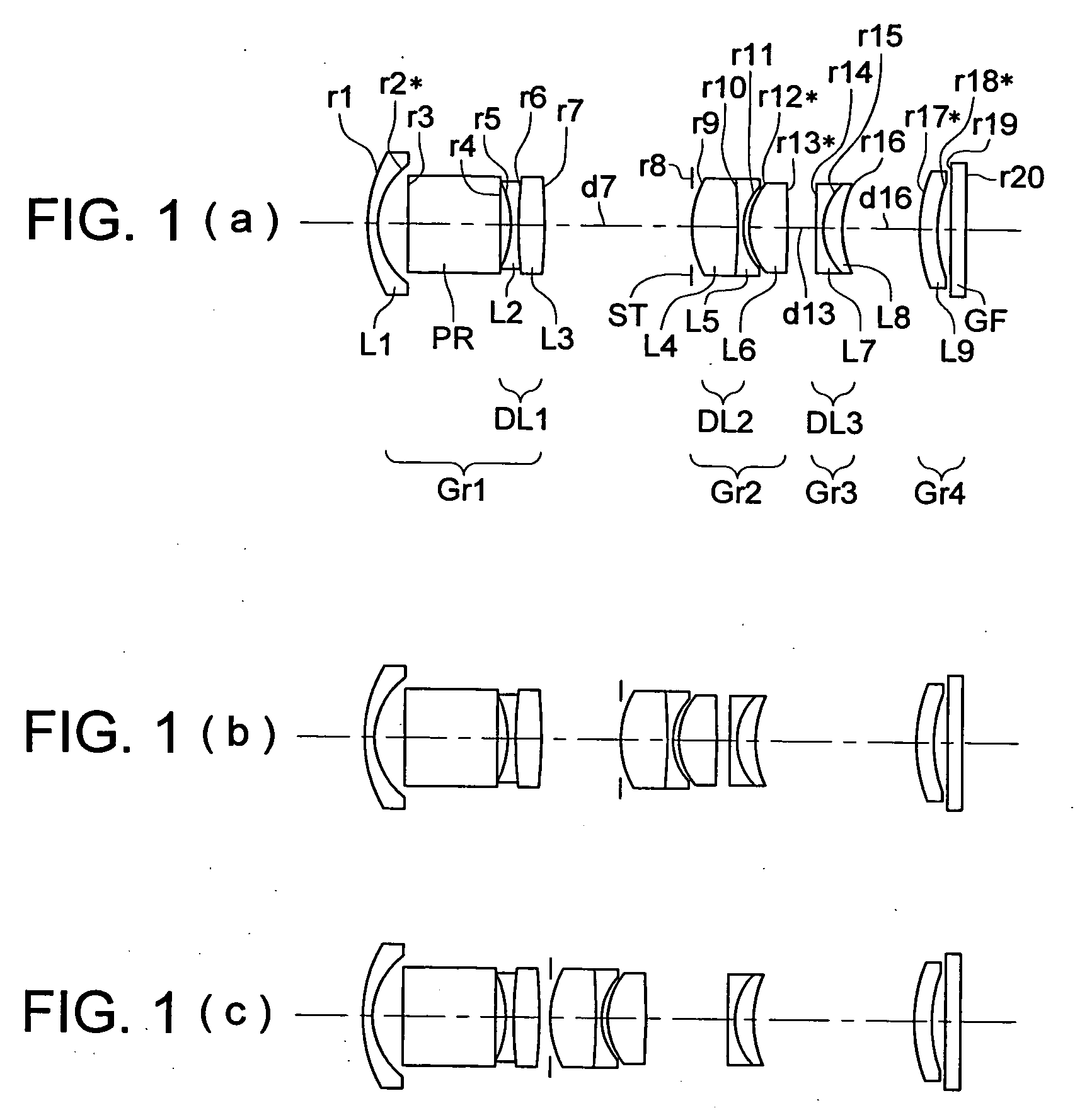
[0066] The numerical example described here corresponds to the lens configuration, which is shown in the embodiment described above and illustrated in FIG. 1. Li (i=1, 2, 3, . . . ) denotes that the lens is positioned at i-th order from the object side; DL1 denotes a first cemented lens configured by a second lens L2 and a third lens L3; DL2 denotes a second cemented lens configured by a fourth lens L4 and a fifth lens L5; and DL 3 denotes a third cemented lens configured by a seventh lens L7 and an eight lens L8.

[0067] In the numerical example, ri (i=1, 2, 3, . . . ) denotes the radius of curvature (mm) of the surface positioned at i-th order from the object side; di (i=1, 2, 3, . . . ) denotes the surface distance between the surfaces of corresponding lenses...


PUM


Abstract

A zoom optical system according to the present invention is provided with, in order from an object side thereof: a first lens group having a negative refractive power; a second lens group having a positive refractive power; a third lens group having a negative refractive power; and a fourth lens group having a positive refractive power. The zoom optical system moves at least the second lens group and the third lens group for zooming operation from a wide-angle end to a telephoto end. The zoom optical system moves the third lens group for a focusing operation. The first lens group is provided with, in order from the object side of the zoom optical system, a meniscus lens having a negative refractive power whose concave surface faces an image side of the zoom optical system, a reflective optical element, and at least one lens.

Description

[0001] This application is based on Japanese Patent Application No. 2005-153686 filed on May 26, 2005 in Japanese Patent Office, the entire content of which is hereby incorporated by reference. FIELD OF THE INVENTION [0002] The present invention relates to a zoom optical system and an image pickup apparatus having the same, the zoom optical system being used for an electronic image pickup apparatus having an image pickup element for converting an optical image formed on a light receiving surface of an image sensor, such as CCD (Charge Coupled Device) and CMOS (Complementary Metal Oxide Semiconductor). BACKGROUND OF THE INVENTION [0003] In recent years, with the raise of the number of pixel of the image pickup element, the demand of an optical system having a lower error sensitivity, which cannot be easily influenced by manufacturing errors, has been growing while maintaining high optical performance with high design flexibility. As technologies in response to the demand, for example...

Claims


Application Information

Patent Timeline
Patent Type & Authority Applications(United States)
IPC IPC(8): G02B15/14
CPCG02B15/177G02B15/144511
Inventor ARIMOTO, TETSUYAJIN, MAKOTOSOUMA, YOSHIHITO
Owner KONICA MINOLTA PHOTO IMAGING
Why Eureka
Try Eureka