Magnetic head for perpendicular magnetic recording and method of manufacturing same
a perpendicular magnetic and recording technology, applied in the direction of head winding construction, data recording, instruments, etc., can solve the problems of difficult to precisely form the pole layer having such a shape, difficult to control the level at which polishing is stopped with precision, and difficult to precisely form the pole layer through the foregoing method
- Summary
- Abstract
- Description
- Claims
- Application Information
AI Technical Summary
Benefits of technology
Problems solved by technology
Method used
Image
Examples
first embodiment
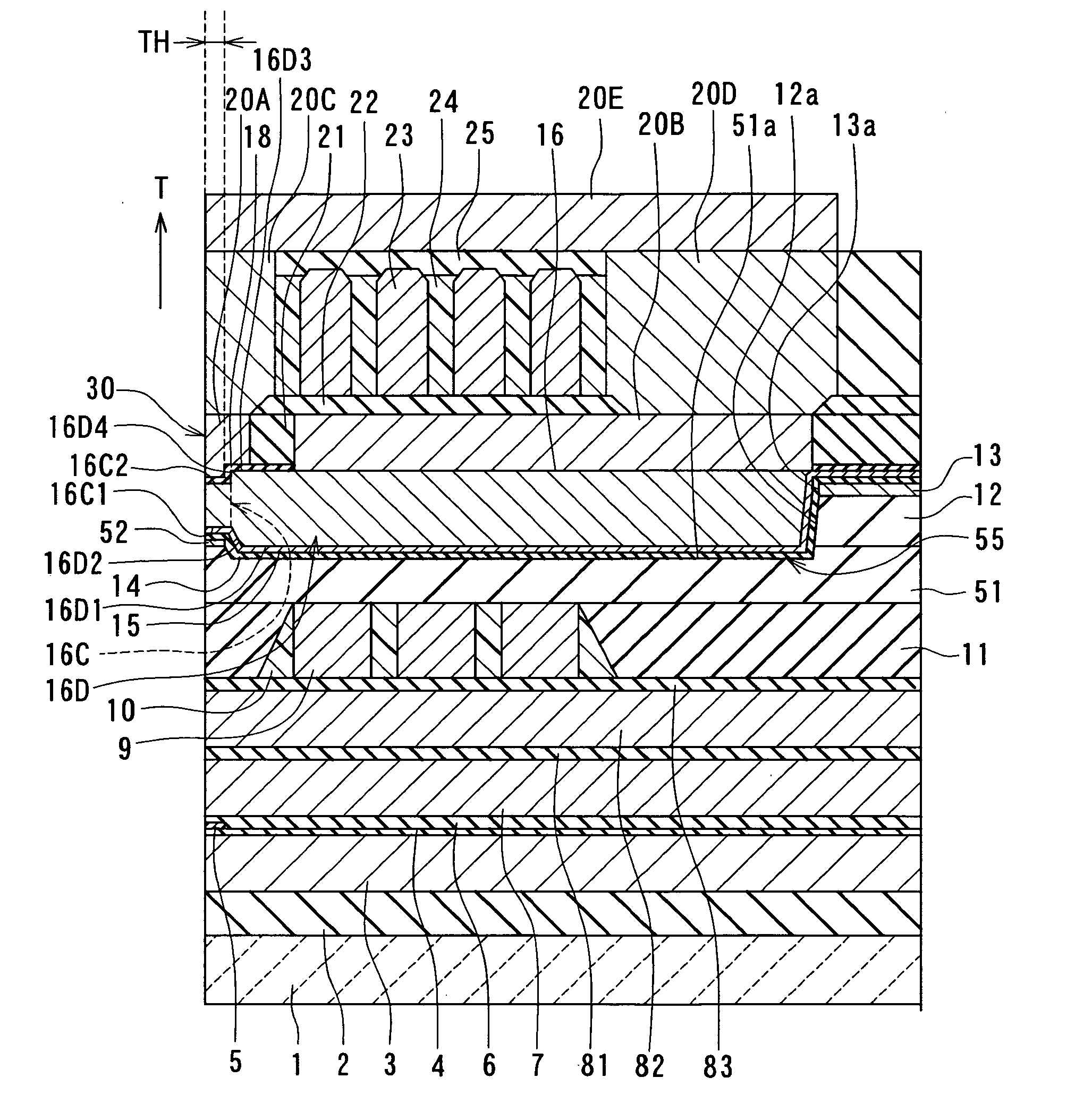
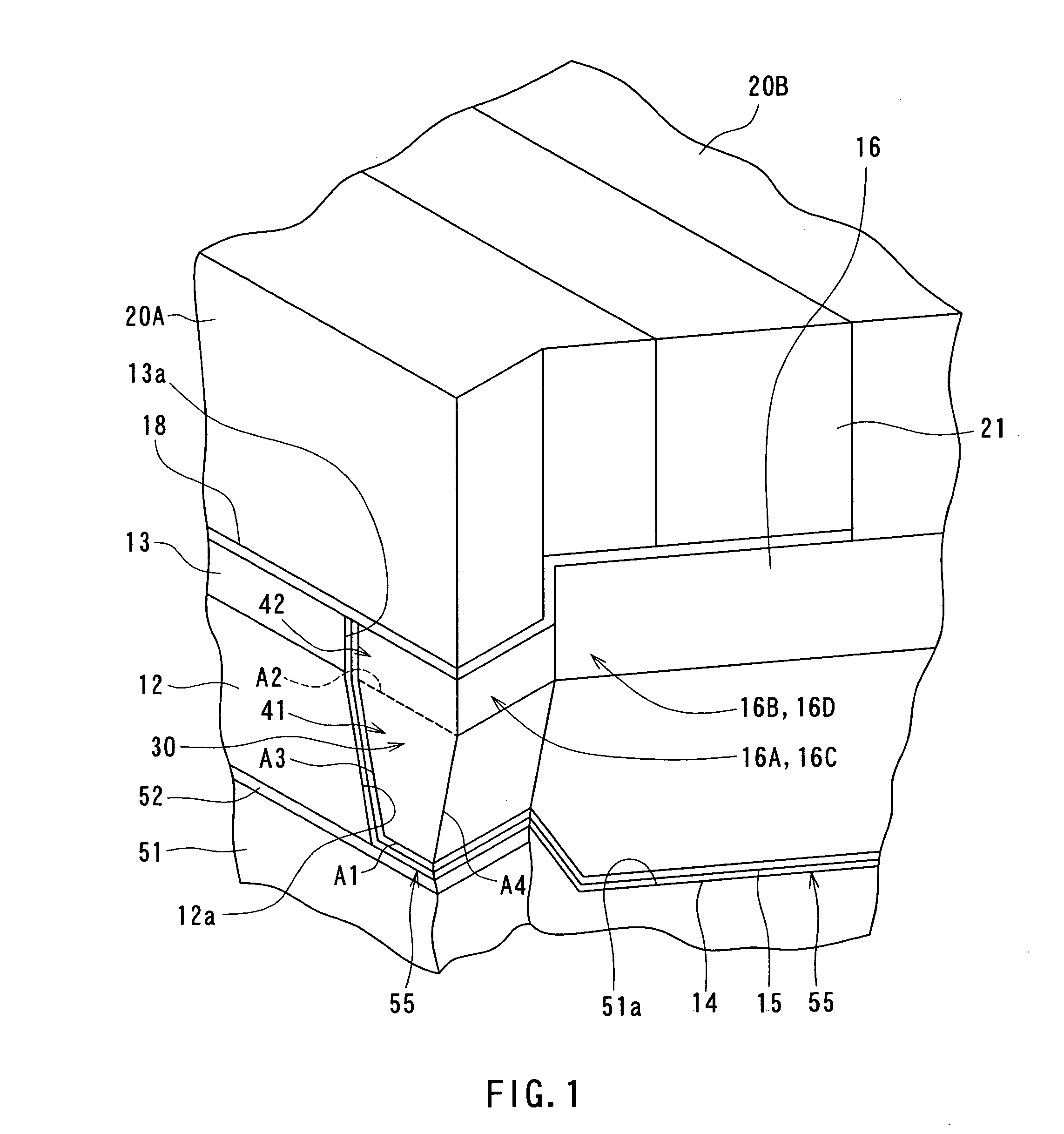
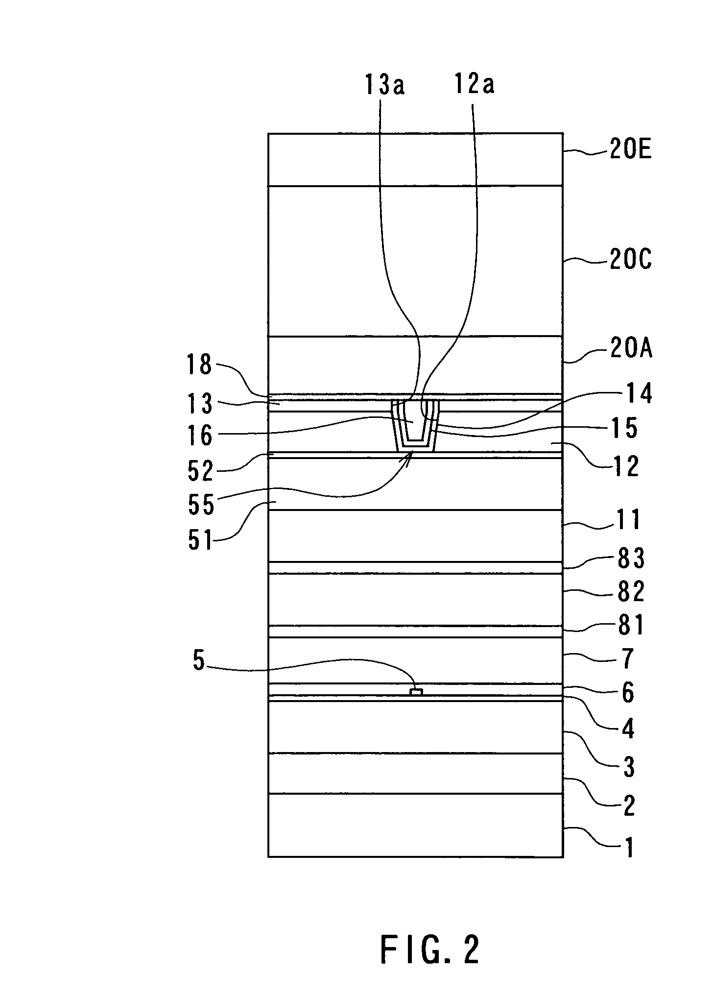
[0098] Preferred embodiments of the invention will now be described in detail with reference to the accompanying drawings. Reference is now made to FIG. 2 and FIG. 3 to describe the configuration of a magnetic head for perpendicular magnetic recording of a first embodiment of the invention. FIG. 2 is a front view for illustrating the medium facing surface of the magnetic head of the embodiment. FIG. 3 is a cross-sectional view for illustrating the configuration of the magnetic head of the embodiment. FIG. 3 illustrates a cross section orthogonal to the medium facing surface and a surface of a substrate. The arrow indicated with T in FIG. 3 shows the direction of travel of a recording medium.
[0099] As shown in FIG. 2 and FIG. 3, the magnetic head for perpendicular magnetic recording (hereinafter simply called the magnetic head) of the embodiment comprises: a substrate 1 made of a ceramic such as aluminum oxide and titanium carbide (Al2O3—TiC); an insulating layer 2 made of an insula...
modification examples
[0179] First to fourth modification examples of the embodiment will now be described. FIG. 17 is a cross-sectional view illustrating a portion of the pole layer 16 near the medium facing surface 30 and a portion around this portion of a magnetic head of the first modification example. In the first modification example, the second front end face 16D4 of the pole layer 16 is tilted with respect to the direction orthogonal to the top surface of the substrate 1 such that the thickness of the pole layer 16 gradually increases as the distance from the medium facing surface 30 increases in the region in which the front end face 16D4 is located. The second front end face 16D4 preferably forms an angle that is equal to or greater than 30 degrees and smaller than 80 degrees with respect to the top surface of the substrate 1. In the first modification example, when a portion of the magnetic layer 16P is etched by ion beam etching to form the surfaces 16C2 and 16D4, the direction in which ion b...
second embodiment
[0186] A magnetic head and a method of manufacturing the same of a second embodiment of the invention will now be described. Reference is now made to FIG. 21A to FIG. 29A and FIG. 21B to FIG. 29B to describe the method of manufacturing the magnetic head of the second embodiment. FIG. 21A to FIG. 29A each illustrate a cross section of a layered structure obtained in the course of manufacturing process of the magnetic head, the cross section being orthogonal to the medium facing surface and the substrate. FIG. 21B to FIG. 29B each illustrate a cross section of a portion of the layered structure near the medium facing surface, the cross section being parallel to the medium facing surface. In FIG. 21A to FIG. 29A and FIG. 21B to FIG. 29B, portions located higher than the coil 9 and the insulating layers 10 and 11 are only shown.
[0187] The method of manufacturing the magnetic head of the second embodiment includes the steps up to the step of flattening the top surfaces of the coil 9 and...
PUM
 Abstract
Description
Claims
Application Information
 - R&D
- Intellectual Property
- Life Sciences
- Materials
- Tech Scout
- Unparalleled Data Quality
- Higher Quality Content
- 60% Fewer Hallucinations
Browse by: Latest US Patents, China's latest patents, Technical Efficacy Thesaurus, Application Domain, Technology Topic, Popular Technical Reports.
© 2025 PatSnap. All rights reserved.Legal|Privacy policy|Modern Slavery Act Transparency Statement|Sitemap|About US| Contact US: help@patsnap.com


