Recording medium cartridge having an accommodation portion for a noncontact-type memory

a technology of noncontact type memory and recording medium, which is applied in the field of recording medium cartridges, can solve the problems of inconvenient operation, inconvenient storage, and high price of parts, and achieve the effect of reducing the difficulty of obtaining the desired recording medium cartridg

Inactive Publication Date: 2006-11-30
FUJIFILM CORP
View PDF1 Cites 4 Cited by
  • Summary
  • Abstract
  • Description
  • Claims
  • Application Information

AI Technical Summary

Benefits of technology

[0029] In view of the above-described problems of the conventional art, a first object of the present invention is to provide a recording medium cartridge such as a magnetic tape cartridge on which is mounted a noncontact-type memory (cartridge memory) having an information storage and signal processing section (IC section) constituted by an IC memory or the like and an antenna section for transmitting and receiving signals, the recording medium cartridge being free from occurrence of malfunction of the noncontact-type memory and an incorrect result of transmitting and receiving of signals, the recording medium cartridge being capable of correctly transmitting and receiving signals to and from the noncontact-type memory with stability.
[0030] In view of the above-described circumstances, a second object of the present invention is to provide a recording medium cartridge designed as a magnetic tape cassette in which a noncontact-type memory can be mounted at such a position as to avoid interference with running of a magnetic tape and not to the structural rigidity of the recording medium cartridge.
[0031] In view of the above-described problems of the conventional art, a third object of the present invention is to provide a recording medium cartridge designed as a magnetic tape cartridge so that a noncontact-type memory (IC memory) can easily be incorporated even in a small cartridge case.
[0032] In view of the above-described circumstances, a fourth object of the present invention is to provide a recording medium cartridge free from the above-described problems of the conventional art, that is, when the recording medium cartridge is loaded in a recording and reproduction apparatus (deck), there is no possibility of a hindrance to transmitting and receiving of data between a noncontact-type memory mounted in the recording medium cartridge and the recording and reproduction apparatus (deck).
[0033] In view of the above-described problems of the conventional art, a fifth object of the present invention is to provide a recording medium cartridge designed as a magnetic type cartridge or the like so that a noncontact-type memory can easily be mounted in the recording medium cartridge, and so that information can easily be written to or read out from the noncontact-type memory.
[0034] In view of the above-described circumstances, a sixth object of the present invention is to provide a cartridge label used by being attached to a recording medium cartridge and designed by considering prevention of damage to a antenna section of a noncontact type memory as well as protection of an IC chip in an IC section of the memory.

Problems solved by technology

Therefore, if a metallic component exists in the vicinity of the antenna of the noncontact-type memory, there is a possibility of failure to suitably supply electric power, which may result in a malfunction, or a possibility of transmitting and receiving of signals being badly influenced to cause incorrect transmitting and receiving of signals.
This method, however, requires high-priced parts which may be low in mechanical and thermal strength, and entails considerable difficulty in obtaining the desired recording medium cartridge in terms of each of the quality and the manufacturing cost of the cartridge.
In the conventional art, there is a second problem that, to attach a cartridge memory to a magnetic tape cassette or a magnetic tape cartridge, the structure, size, etc., of which are specified in detail as described above, for the purpose of indicating the contents of information recorded on a magnetic tape accommodated in the cartridge, it is necessary to design an attachment structure with great care so as to avoid interference with running of the magnetic tape and not to cause a reduction in structural rigidity.
There is a third problem of the conventional art described below.
Further, in recent magnetic tape cartridges, the diameter of the magnetic winding is increased for the purpose of increasing the recording capacity, and it is more difficult to incorporate a cartridge memory (memory IC) in such cartridges on the basis of the conventional incorporation method.
In the conventional art, there is a fourth problem that, in a case where a cartridge memory is mounted in a recording medium cartridge such as a magnetic tape cartridge by an arrangement system such as that in the illustrated example described above, there is a possibility of a hindrance to transmitting and receiving of data between the cartridge memory and a recording and reproduction apparatus (deck) for a reason relating to the recording medium cartridge on the mount side when the recording medium cartridge is set in the recording and reproduction apparatus.
There is a fifth problem of the conventional art described below.
After a cartridge memory has been incorporated in a magnetic tape cartridge in the manner described above with respect to the illustrated example, it may be found to be defective by an operation check.
Also, since cartridge memories are high-priced, they may be reused if the magnetic tape cartridge in which the cartridge memory becomes unusable for some reason.
Reuse of cartridge memories requires troublesome operations of disassembling magnetic tape cartridges to take out the cartridge memories.
A sixth problem of the conventional art relates to a method for mounting a cartridge memory in a recording medium cartridge other than that described above with reference to FIG. 31.
The cassette label in the above-described conventional art entails a drawback in that, when a user writes on the cassette label information on the contents of a recording in the video tape cassette, the user may damage the IC chip (IC memory) in the cartridge memory in the cartridge label by, for example, applying a high pressure to the point of a ball-point pen.
The sixth problem of the conventional art resides in that, although the cartridge label in the art disclosed in the above-described publication was designed by considering protection of the IC chip in the cartridge memory, it is, in fact, also important to consider prevention of damage (causing disconnection or the like) to the antenna conductor (coil) in the antenna section, and the above-described kind of cartridge label has not been designed by considering protection of the antenna section for preventing such damage.

Method used


Image

  • Recording medium cartridge having an accommodation portion for a noncontact-type memory
  • Recording medium cartridge having an accommodation portion for a noncontact-type memory
  • Recording medium cartridge having an accommodation portion for a noncontact-type memory

Examples


first embodiment

[0188] the recording medium cartridge in the third mode of implementation of the present invention will be described.

[0189] Referring to FIG. 16, in the first embodiment, a cartridge memory 30 (see FIG. 5) curved so as to conform to the circumferential (outermost) configuration of one magnetic tape winding accommodated in the cartridge case when the diameter of the tape winding is maximized is placed on one circumference along with a side wall recess 12k and a wall portion (hereinafter referred to as “reel area rib”) 12e formed so as to have a ridged shape, thereby forming reel area inner wall surfaces.

[0190] The cartridge memory 30 has such a rigidity as to be able to be mounted by after being bent so as to have a predetermined curvature, as described above. The corresponding corner portion of the cartridge memory 30 is higher in strength and can be suitably used as a portion on which the cartridge memory 30 is mounted. Also, at this corner portion, a certain gap is formed between...

second embodiment

[0192] A second embodiment in this mode of implementation will next be described.

[0193] Referring to FIG. 17, in the second embodiment, a cartridge memory 30 which, like that in the first embodiment, is curved so as to conform to the circumferential (outermost) configuration of one magnetic tape winding accommodated in the cartridge case when the diameter of the tape winding is maximized is mounted in place of a cut portion of the reel area rib 12e of the lower half 12, the curvature of the cartridge memory 30 being adjusted to that of the reel area rib 12e. Thus, the cartridge memory 30 forms (a portion of) the reel area inner wall surface.

[0194] The reel area wall portion formed by replacing a portion of the reel area rib 12e with the cartridge memory 30 becomes weak in strength. However, since the reel area rib 12e is cut only partially, and since it is possible to leave an end portion of the reel area rib 12e, a sufficient strength of the reel area rib 12e can be maintained.

[0...

third embodiment

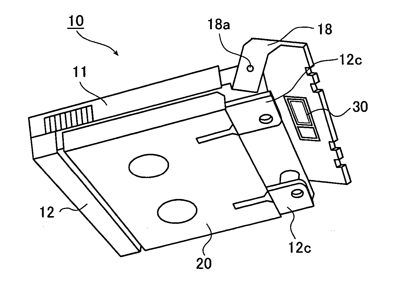
[0212]FIG. 20 shows a state in which the above-described cartridge memory 30 is mounted in the above-described magnetic tape cartridge 10 in a third embodiment in this mode of implementation. In this embodiment, the cartridge memory 30 is mounted on a lower (inner) surface portion of the upper half 11 of the cartridge 10 corresponding to an opening 46 formed when the slider 20 recedes. In mounting the cartridge memory 30, the cartridge memory 30 is fixed by a screw passed through its portion inside the antenna section 30b.

[0213] Preferably, in mounting the cartridge memory 30 in the lower (inner) surface portion of the upper half 11 of the cartridge 10, the peripheral portion of the position at which the cartridge memory 30 is attached is recessed sufficiently deeply for the purpose of avoiding unnecessary interference with the magnetic tape 16 when it runs in the magnetic tape cartridge 10.

[0214] In the thus-constructed magnetic tape cartridge 10 of this embodiment, the opening 4...


PUM

PropertyMeasurementUnit
angleaaaaaaaaaa
densityaaaaaaaaaa
sizeaaaaaaaaaa

Abstract

The recording medium cartridge includes a cartridge case containing a recording medium and a noncontact-type memory having an IC section for storing information and performing signal processing and an antenna section for transmitting and receiving signals. In one cartridge, the antenna section of the memory is placed in a region furtherest from metallic parts. In other cartridge, the memory is mounted in an accommodation portion recessed one step relative to a surrounding portion, in such a way that a portion of an inner wall of a real area for accommodating a magnetic tape corresponding to the recording medium is formed, in such a position as to be exposed when the cartridge is loaded into a drive, or in recess formed in an outer surface of a case. The cartridge label is attached to the cartridge and contains the noncontact-type memory. At least an antenna section protective indication for indicating an information writing area other than the area on an antenna coil of the antenna section is provided on the cartridge label.

Description

[0001] This is a divisional of application Ser. No. 09 / 851,991 filed May 10, 2001. The entire disclosure of the prior application, application Ser. No. 09 / 851,991 is considered part of the disclosure of the present application and is hereby incorporated by reference.BACKGROUND OF THE INVENTION [0002] 1. Field of the Invention [0003] The present invention relates to a recording medium cartridge which incorporates a magnetic recording medium, such as a magnetic tape or a magnetic disk, or an optical recording medium, such as a magneto-optical disc or an optical disc, and which is, for example, a magnetic tape cassette or a magnetic tape cartridge. That is, the present invention belongs to the technical field of a recording medium cartridge formed by accommodating a recording medium, e.g., a magnetic recording medium, such as a magnetic tape or a magnetic disk, or an optical recording medium in a cartridge case. More particularly, the present invention relates to a recording medium car...

Claims


Application Information

Patent Timeline
Patent Type & Authority Applications(United States)
IPC IPC(8): G11B23/02G11B23/03G11B23/087G11B23/40
CPCG11B23/0305G11B23/40G11B23/08714
Inventor HIRAGUCHI, KAZUOTAKAHASHI, DAISUKEONMORI, SHOZOASHIKAWA, TERUO
Owner FUJIFILM CORP
Why Eureka
Try Eureka