Optical waveguide sheath

Active Publication Date: 2006-11-30
INVUITY
View PDF26 Cites 46 Cited by
  • Summary
  • Abstract
  • Description
  • Claims
  • Application Information

AI Technical Summary

Benefits of technology

[0019] It is also possible to apply the structured technology to deflect light as well as focus it into a particular shape. Microstructure may be applied to the back and or the front of a refractive element to deflect the beam as well as shape it. Microstructure surfaces may also be combined with one or more air gaps and or conventional surface shaping to achieve desired optical performance.
[0020] In a still further aspect of the present disclosure one or more surfaces i

Problems solved by technology

However, there are complications using optical fiber illumination in flexible endoscope applications.
Although the cost of raw glass or plastic fiber is relatively inexpensive, the cost of assembling the fiber into an endoscope tube may be high.
Optical fiber is extremely fragile and brittle.
During the assembly process or in the field after many sterilization cycles, optical fiber may start to break down and degrade.
Since the fiber is integrated into endoscopes, any damage to the fiber optics also results in damage to the scope, thus causing an expensive overhaul.
A significant challenge in many endoscopic procedures is ca

Method used


Image

  • Optical waveguide sheath
  • Optical waveguide sheath
  • Optical waveguide sheath

Examples


Embodiment Construction

[0042] The following disclosure generally refers to an optical waveguide and associated elements for conduction of light. This discussion is for example and the following disclosure may also be suitable for any electromagnetic radiation. The cross-sections illustrated are generally circular and may also adopt any suitable geometry.

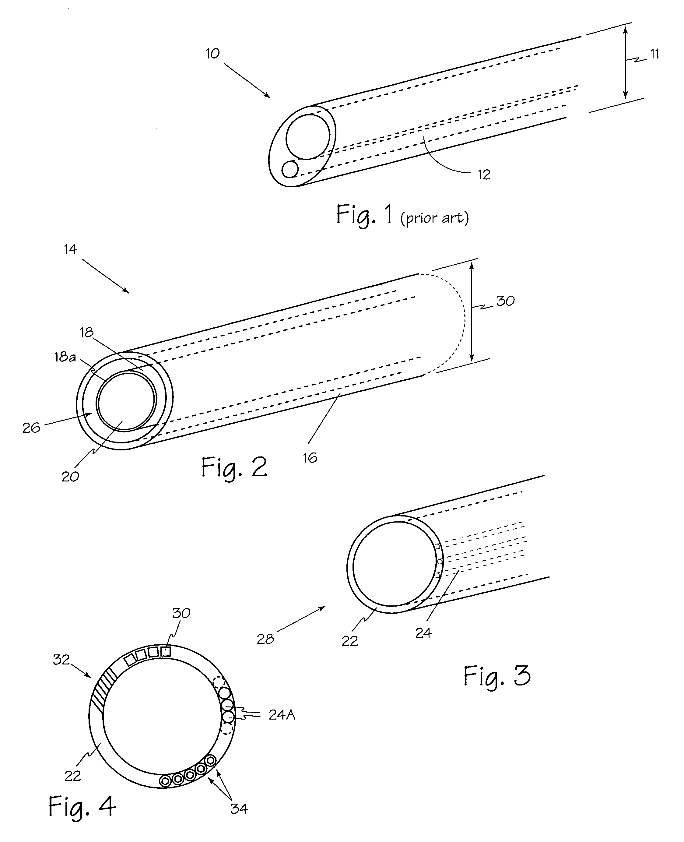
[0043] Referring now to FIG. 2, optical waveguide system 14 may accommodate any suitable surgical instrument such as endoscope 18 which is encased, enclosed or otherwise surrounded by optical waveguide sheath 16. An optical waveguide sheath according to the present disclosure is a generally annular or cylindrical shaped structure and may be manufactured separately and may be a single use device. In the event of a failure of an optical waveguide such as optical waveguide sheath 16, a replacement may be introduced immediately. Flow path 26 is created between endoscope 18 and optical waveguide sheath 16. Flow path 26 may be used for any suitable service such...


PUM


Abstract

The illumination system described below comprises an arthroscope, endoscope or other suitable surgical tool and an attachable cannula comprising a transparent or semi-transparent material capable of carrying light from the proximal end of the cannula to the distal end of the cannula, thereby illuminating the surgical field. The surgical field is thus illuminated through components that do not occupy space that may otherwise by used for the optics of the arthroscope. The arthroscopic illumination system further comprises one or more illumination sources disposed at the proximal end of the cannula. The illumination source may be optically coupled with the cannula at the hub or other appropriate location. The cannula comprises a sterilizable polymer which functions as a waveguide. A waveguide is a material medium that confines and guides light. When in use, the light source connected to the hub provides light which may be guided to the distal end of the cannula or any other suitable location. Thus, the sheath provides structure-guided illumination resulting in the illumination of the surgical site.

Description

RELATED APPLICATION [0001] The present application claims priority from copending U.S. provisional patent application Ser. No. 60 / 668,442 filed Apr. 4, 2005 and copending U.S. provisional patent application Ser. No. 60 / 724,717 filed Oct. 7, 2005.FIELD OF THE INVENTIONS [0002] The present invention relates generally to the field of surgical illumination and more specifically to optical waveguide endoscope illumination. BACKGROUND OF THE INVENTION [0003] Currently optical fiber illumination elements such as element 12 shown in FIG. 1 are used exclusively in medical illumination where small packaging is critical. Devices such as endoscope 10 are the most common devices that currently use optical fiber illumination. Due to its compact size, optical fiber is an excellent choice for rigid endoscope illumination. However, there are complications using optical fiber illumination in flexible endoscope applications. [0004] Although the cost of raw glass or plastic fiber is relatively inexpens...

Claims


Application Information

Patent Timeline
IPC IPC(8): A61B1/06F21S4/00F21V5/00G02B6/06
CPCA61B1/00135A61B1/0607A61B1/07A61B1/3132A61B17/3421A61B19/5202G02B23/2469A61B1/00103A61B19/52A61B90/30A61B90/36
Inventor VAYSER, ALEXTRAUNER, KENNETHGASSON, JONGREY, TOM
Owner INVUITY
Why Eureka
Try Eureka