
Stent with flexible sections in high strain regions

a flexible section and stent technology, applied in the field of stents, can solve the problems of stent struts that are susceptible to cracking, localized portions of the stent pattern subject to substantial deformation are the most susceptible to failure, and the stent pattern is subject to substantial deformation. , to achieve the effect of increasing the resistance to strain, reducing the risk of fracture, and increasing the flexibility

Inactive Publication Date: 2006-11-30
ABBOTT CARDIOVASCULAR
View PDF32 Cites 61 Cited by
  • Summary
  • Abstract
  • Description
  • Claims
  • Application Information

AI Technical Summary

Benefits of technology

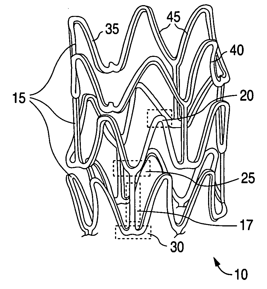
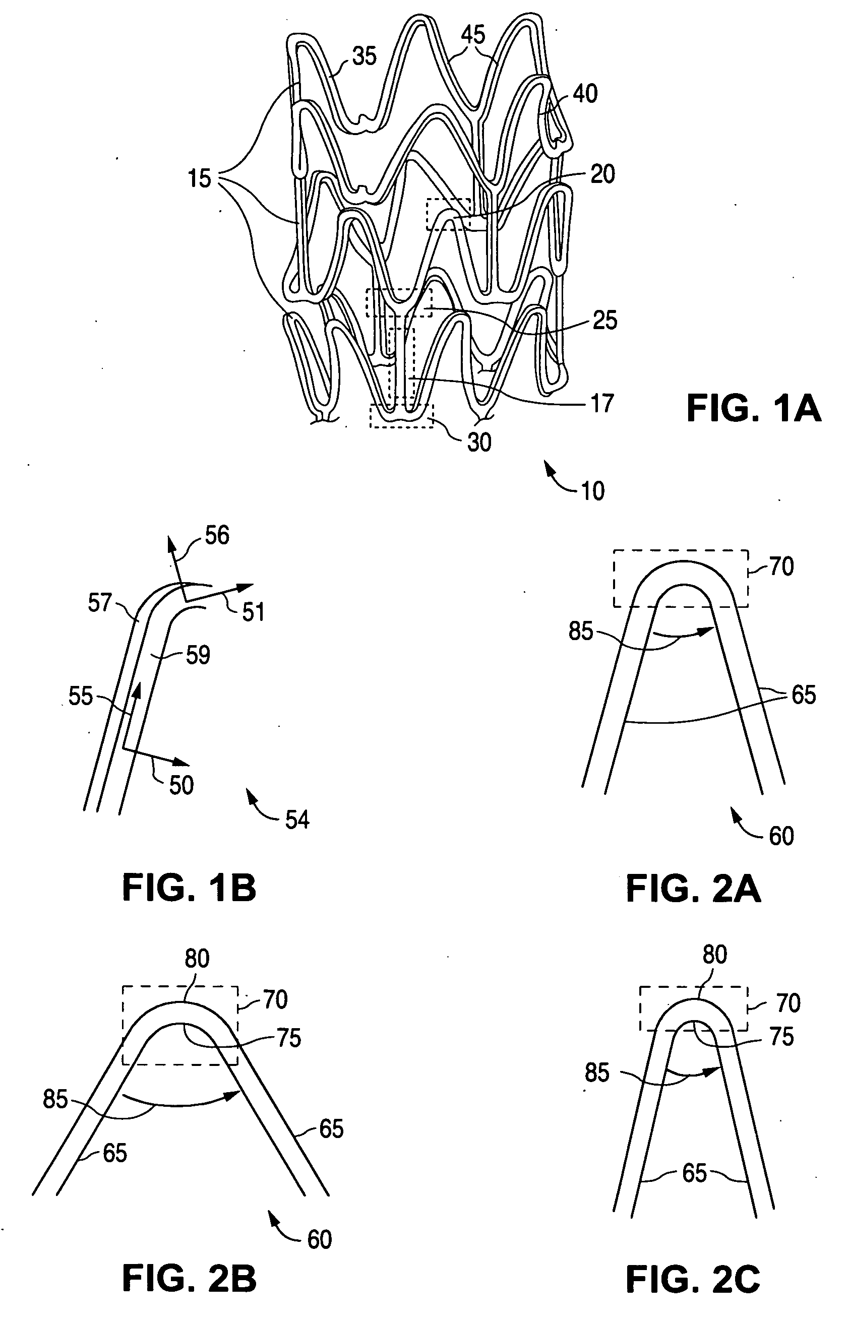
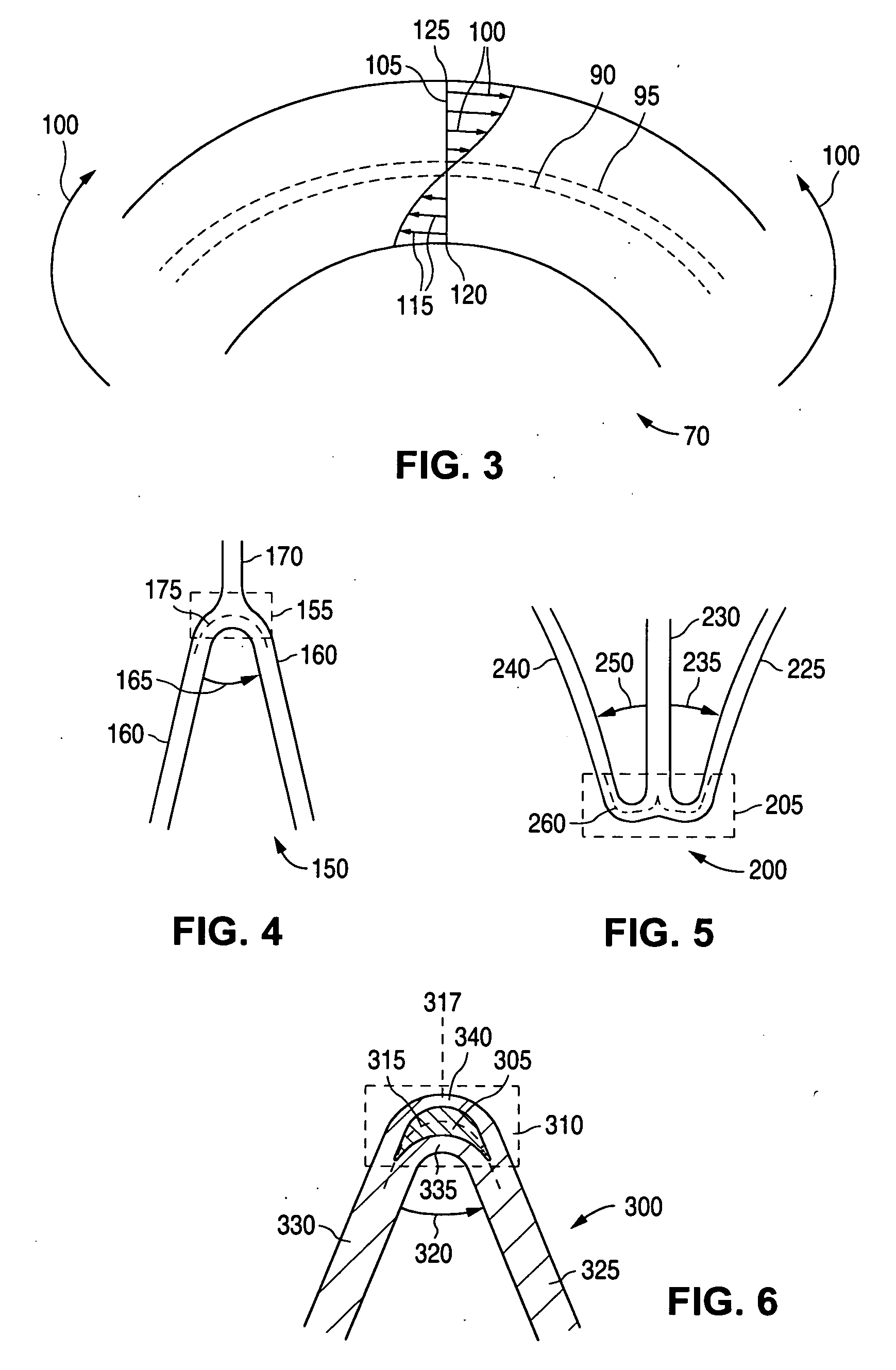
[0013] The present invention is directed to embodiments of a stent having structural elements that may include a flexible or deformable section embedded within a high strain region of a structural element. The flexible section may extend through the high strain region from an abluminal surface of the high strain region to a luminal surface of the high strain region. The flexible section may have a greater flexibility than a majority of the structural element outside of the flexible section. The high strain region may have a higher strain as compared to other regions of the structural element when the stent is subjected to an applied stress during use. The section may be selectively positioned to increase resistance to strain in the high strain region to inhibit or prevent fracturing in the high strain region when subjected to the applied stress during use.
[0014] A further aspect of the invention is directed to embodiments of a method of forming a stent. The method may include forming a cavity within a high strain region of a structural element. The cavity may extend through the high strain region from an abluminal surface of the high strain region to a luminal surface of the high strain region. The high strain region may include a higher strain as compared to other regions of the structural element when the stent is subjected to an applied stress during use. The method may further include forming a flexible section within all or substantially all of the cavity. The flexible section may have a greater flexibility than a majority of the structural element outside of the flexible section. The section may be selectively positioned to reduce an amount of strain in the high strain region to inhibit or prevent fracturing in the high strain region when subjected to the applied stress during use.

Problems solved by technology

Such movement typically results in substantial deformation of localized portions of the stent's structure.
However, a potential problem with polymeric stents is that their struts may be susceptible to cracking during crimping and expansion especially for brittle polymers.
The localized portions of the stent pattern subjected to substantial deformation tend to be the most vulnerable to failure.

Method used


Image

  • Stent with flexible sections in high strain regions
  • Stent with flexible sections in high strain regions
  • Stent with flexible sections in high strain regions

Examples


example

[0088] Some embodiments of the present invention are illustrated by the following examples. The examples are being given by way of illustration only and not by way of limitation. The parameters are not to be construed to unduly limit the scope of the embodiments of the invention.

[0089] A structural element may be composed of a high modulus polymer such as poly(L-lactide), poly(D,L-lactide), or poly(ε-caprolactone), mixtures thereof, or copolymers thereof. A flexible section may composed of flexible polymers such as poly(D,L-lactide)-polyethylene glycol-poly(D,L-lactide) triblock copolymer, 70 / 30 poly(L-lactide-co-trimethylene carbonate), or polyanhydrides.


PUM


Abstract

A stent for treating a bodily lumen with a flexible section in a high strain region is disclosed. A flexible section may be selectively positioned to reduce an amount of strain in the high strain region when subjected to the applied stress during use to inhibit or prevent fracturing in the high strain region.

Description

BACKGROUND OF THE INVENTION [0001] 1. Field of the Invention [0002] This invention relates to implantable medical devices, such as stents. In particular the invention relates to stents having structural elements with flexible or deformable sections that increase the crack resistance of the stent during use. [0003] 2. Description of the State of the Art [0004] This invention relates to radially expandable endoprostheses, which are adapted to be implanted in a bodily lumen. An “endoprosthesis” corresponds to an artificial device that is placed inside the body. A “lumen” refers to a cavity of a tubular organ such as a blood vessel. [0005] A stent is an example of such an endoprosthesis. Stents are generally cylindrically shaped devices, which function to hold open and sometimes expand a segment of a blood vessel or other anatomical lumen such as urinary tracts and bile ducts. Stents are often used in the treatment of atherosclerotic stenosis in blood vessels. “Stenosis” refers to a nar...

Claims


Application Information

Patent Timeline
IPC IPC(8): A61F2/06
CPCA61F2/91A61F2/915A61F2250/0029A61F2002/91575A61F2002/91533
Inventor GALE, DAVID C.KLEINE, KLAUSABBATE, ANTHONY J.ATLADOTTIR, SVAVA MARIAPACETTI, STEPHEN
Owner ABBOTT CARDIOVASCULAR
Learn More