Standing station

a technology of standing station and patient body, applied in the field of health care industry, can solve the problems of unsettling patients and their caregivers, limited maneuverability relative to beds, wheelchairs, chairs, and patient falls

Inactive Publication Date: 2006-12-07
WOODWARD ERIC EUGENE
View PDF15 Cites 11 Cited by
  • Summary
  • Abstract
  • Description
  • Claims
  • Application Information

AI Technical Summary

Benefits of technology

[0033] The general idea of this invention is to give the care-provider a compact tool that can roll a semi-kneeling patient from one place to another with minimal risk of injury to either person.
[0034] The design of the standing station is based on anatomic, physiologic, kinesiologic, psychologic and mechanical principles. It facilitates human function by strategically placing the following structural elements: 1. a standing platform that is essentially at floor level to maximize mechanical advantage for standing from a standard height chair, bed, wheelchair or commode; 2. a leg abutment pad that allows the patient to semi-kneel and positions the patient's heels near the back edge of the standing platform; 3. a series of grab bars at graduated distances and heights to accommodate different body types, sizes and abilities; 4. a frame and standing platform designed to abut firmly against beds, chairs, wheelchairs and commodes; 5. a wheel mount design that does not protrude past the back edge of the standing platform so the standing station can abut to or move sideways relative to beds, wheelchairs and commodes reguardless of their design; 6. an uppermost section of the frame that serves as both guard rail and grab bar; and 7. a peg on the uppermost section of the frame that allows an ordinary bed sheet to be used to secure the patient.
[0035] The standing station is stabilized by only one caregiver to prevent tipping while the patient transitions from sitting to semi-kneeling. Once the patient is semi-kneeling on the device, it is inherently stable and can be rolled to a new location.

Problems solved by technology

Caregiver injuries and patient falls are a major problem in the health-care industry.
This scenario frequently results in injuries.
Mechanical lift devices may be available to caregivers, but these devices are used reluctantly for several reasons.
They have large bases that are stabile but have limited maneuverability relative to beds, wheelchairs, chairs or commodes.
The safety of the patient often relies on the integrity of ropes, chains, belts or slings which is unsettling to patients and their caregivers.
If it doesn't save time, care providers will choose a quicker solution even if it carries a higher risk of injury.
First, the platform the patient stands on is too high above floor level.
This makes standing from a chair more difficult.
Second, this device can allow the patients knees to buckle unexpectedly.
U.S. Pat. No. 5,257,425 has the same two problems as the previous example plus maneuverability problems caused by an elongated base that extends horizontally outward past the back edge of the standing platform.
This base makes it impossible to move the device laterally when it is positioned in front of a chair, bed, wheelchair or commode.
The maneuverability of this device would be limited by low bed frames or obstacles found under hospital beds such as power cords and brake levers.
The search revealed mechanical lift devices with leg / knee abutment pads, but they place patients in nonfunctional positions.
For example, U.S. Pat. No. 4,918,771 does not allow the patient to lean forward over his / her feet when preparing to stand.
It allows some forward leaning, but the leg abutment pad has a strong spring that does not facilitate a forward weight shift when beginning to stand.
This is fine for transporting patients longer distances, but cumbersome for quick transfers at the bedside.
One problem with the ARJO Stedy is that it's design is geared toward the sitting patient.
A tall patient could easily lose his / her balance while standing in the device, especially if the brakes are not locked and the device is being moved.
If there is not enough clearance under the bed or chair, the elongated base will not fit under so the device can't be used.

Method used


Image

  • Standing station
  • Standing station
  • Standing station

Examples


Embodiment Construction

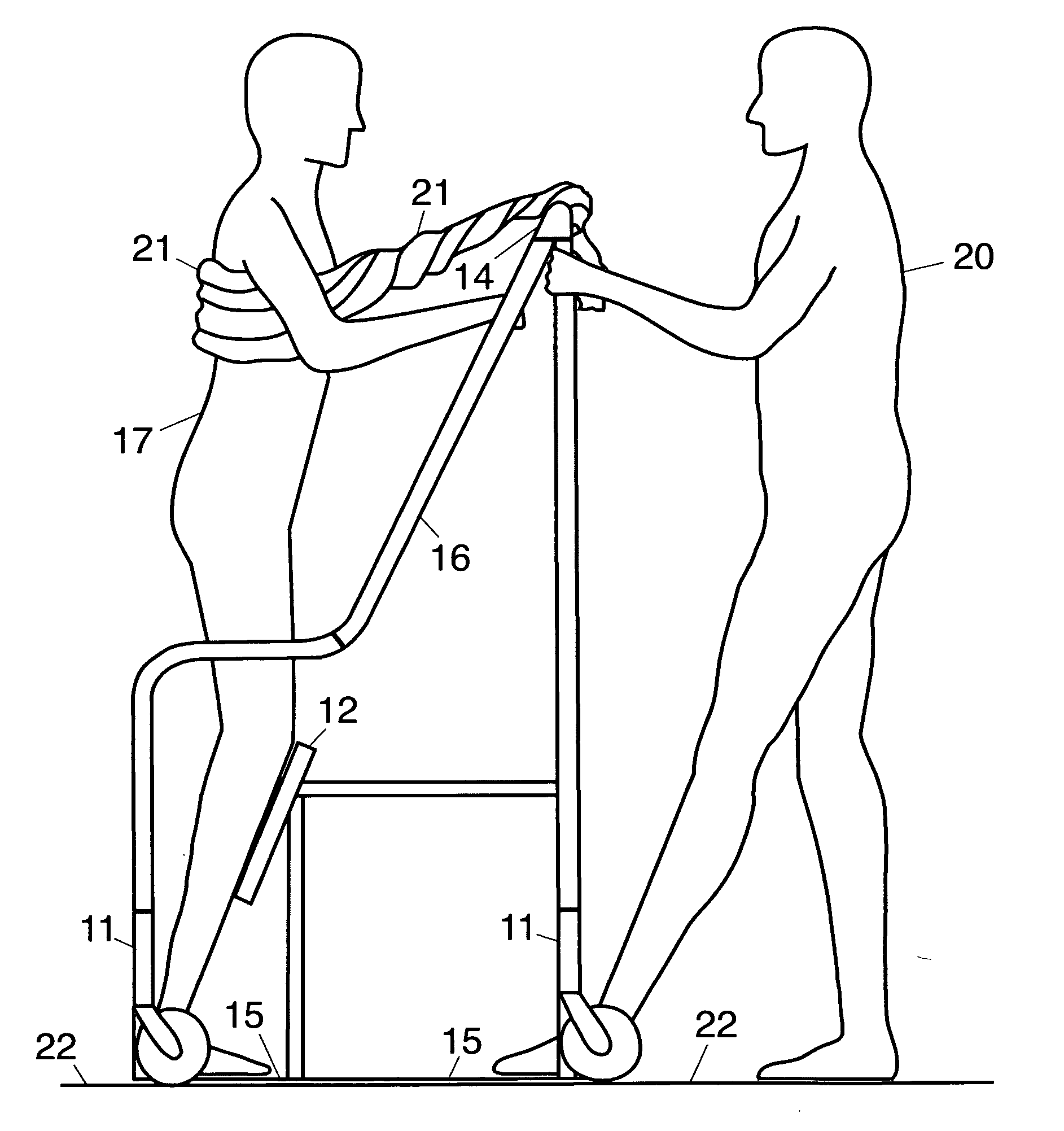
[0039] The drawings depict a standing station generally designated 10.

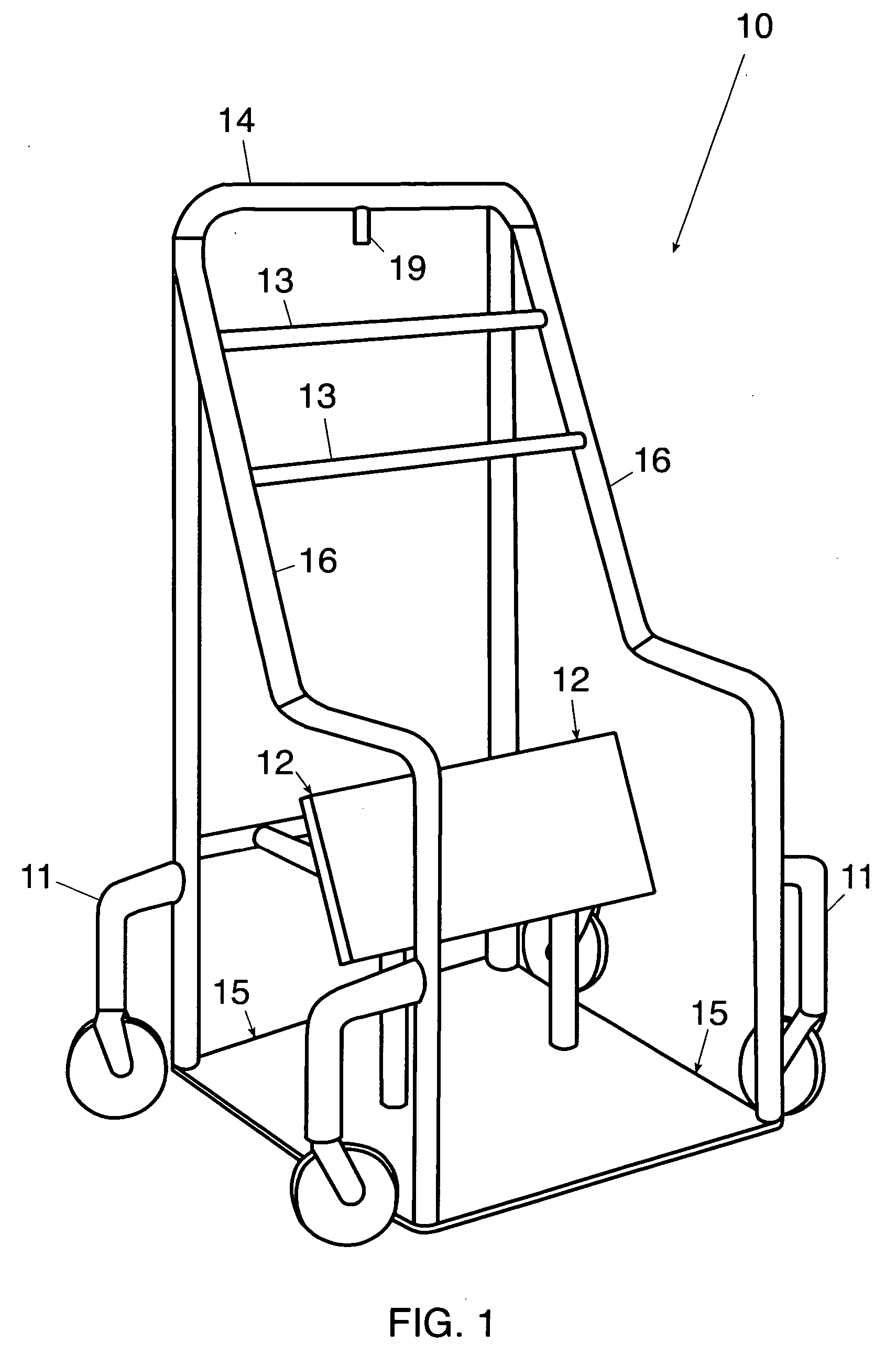
[0040]FIG. 1 depicts the preferred embodiment of the standing station 10. The slanted sections of the frame 16 are supporting the grab bars 13. The uppermost section of the frame 14 has a peg 19 that enables the caregiver to secure the patient with an ordinary bedsheet.

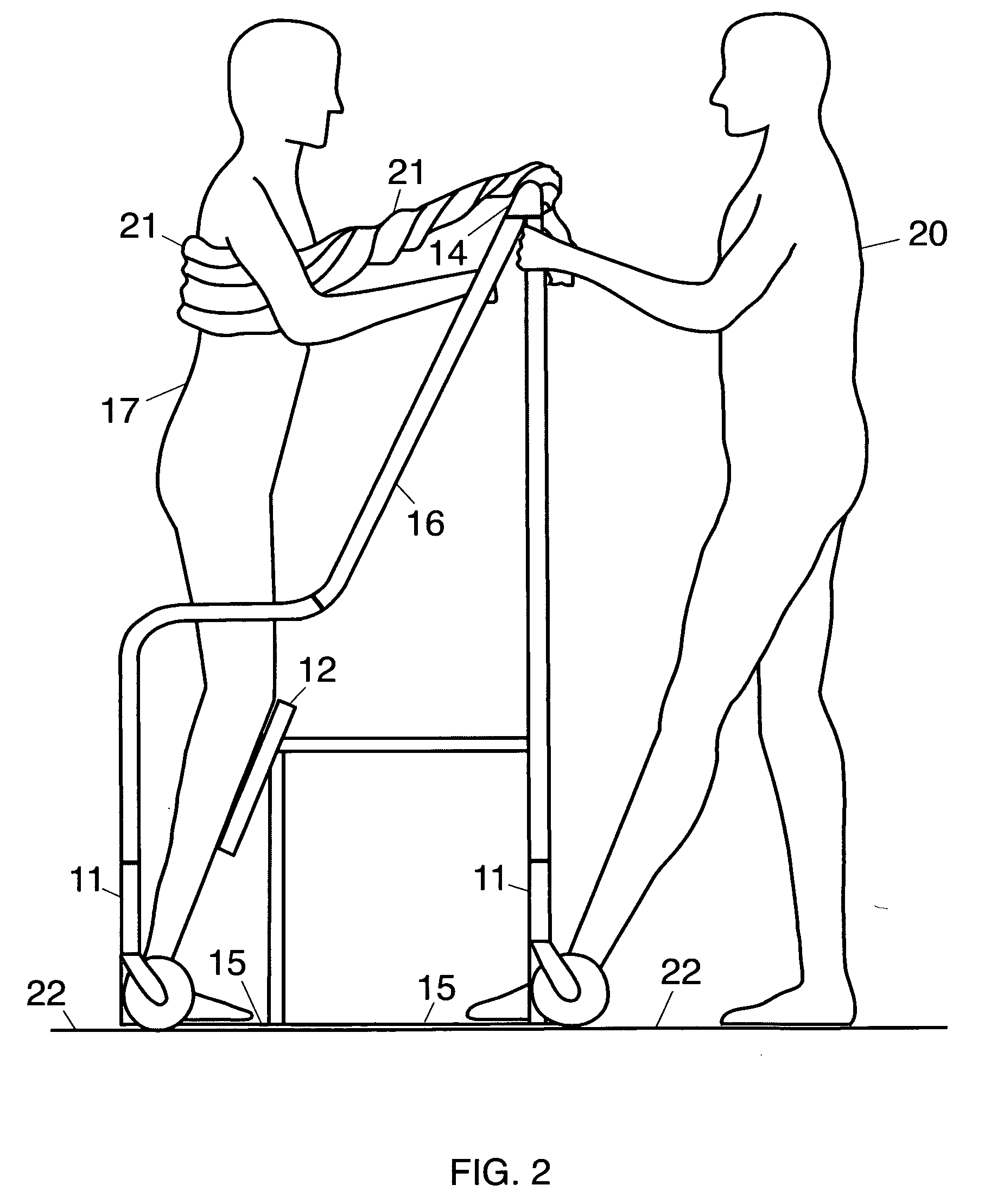
[0041]FIG. 2 depicts a patient semi-kneeling on the standing station while the caregiver holds onto the frame of the device and stabilizes it with one foot. The standing platform 15 is essentially at floor level 22, and the wheel mounts 11 do not extend past the back edge of the standing platform. This allows the standing station to be moved sideways relative to chairs, commodes, beds and wheelchairs without moving away from the safety of the seating surface. It also means that the maneuverability of the standing station will be unaffected by power cords, brake levers or other obstacles found under hospital beds. The leg abutment pad 12 allows the...


PUM


Abstract

The standing station is used as a patient transfer tool, or as a strengthening tool. The standing station uses a leg abutment pad as a weight bearing surface that allows the patient to semi-kneel during transfers and essentially eliminates the risk of patient falls. The standing station uses an ordinary bed sheet to secure the patient. The standing station's wheel mounts do not extend past the back edge of the standing platform so it has unrestricted mobility relative to beds, chairs, wheelchairs and commodes reguardless of their design.

Description

CROSS-REFERENCE TO RELATED APPLICATIONS U.S. Pat. No. 6,643,869 Nov. 11, 2003 Sloan, Jr. et al. U.S. Pat. No. 5,711,044 Jan. 27, 1998 Newman, et al. U.S. Pat. No. 5,509,152 Apr. 23, 1996 Kippes U.S. Pat. No. 5,257,425 Nov. 2, 1993 Shinabarger U.S. Pat. No. 4,918,771 Apr. 24, 1990 James U.S. Pat. No. 4,435,863 Mar. 13, 1984 Lerich U.S. Pat. No. 4,279,043 Jul. 21, 1981 SaundersSTATEMENT REGUARDING FEDERALLY SPONSORED RESEARCH OR DEVELOPMENT [0001] (Not Applicable) REFERENCE TO SEQUENCE LISTING, A TABLE, OR A COMPUTER PROGRAM LISTING COMPACT DISC APPENDIX (not applicable) BACKGROUND OF THE INVENTION [0002] Caregiver injuries and patient falls are a major problem in the health-care industry. In healthcare facilities, assisting weak patients to stand is usually accomplished by pulling the patient up by the arms. If the patient's knees buckle unexpectedly, the patient falls to the floor unless the caregivers are strong enough lower the patient to the floor safely, or carry the pati...

Claims


Application Information

Patent Timeline
Patent Type & Authority Applications(United States)
IPC IPC(8): A61G7/14
CPCA61G7/10A61G7/1023A61G7/1038A61H3/008A61G7/1096A61G2200/34A61G2200/36A61G7/1046
Inventor WOODWARD, ERIC EUGENE
Owner WOODWARD ERIC EUGENE
Why Eureka
Try Eureka