Impact resistant breaker deployment system for an excavating machine

a technology of breaker and deployment system, which is applied in the field of impact resistance breaker deployment system of excavating machine, can solve the problems of laborious and time-consuming, difficult and laborious actual excavation tasks of the operator, and the need for laborious /breaker/bucket change-out, of course, to achieve the effect of avoiding side plate distortion, easy disassembly of the trunnion assembly, and new and durabl

Inactive Publication Date: 2006-12-07
RECS
View PDF0 Cites 11 Cited by
  • Summary
  • Abstract
  • Description
  • Claims
  • Application Information

AI Technical Summary

Benefits of technology

[0016] A primary advantage of the present invention's various embodiments is that it provides an extremely durable trunnion assembly for pivotal connection of the tool to the bracket. Another advantage is that it provides a new and durable stop mechanism, configured to avoid distortion of the side plates. Another advantage is that it is easy to disassemble the trunnion assembly to replace or service tool components. Another advantage is that it provides a reliable and effective means for lubricating the bearing surface of the trunnion assembly to ensure reliable operation of the tool.
[0017] In accordance with a preferred embodiment thereof, an excavating tool system for use on an excavating machine is provided. A bracket is located on the underside of a boom stick. The bracket has a first pivot and a second pivot. The first pivot is a trunnion. An excavating tool is pivotally secured at one end to the trunnion. The excavating tool has a third pivot located thereon between its one end and its opposite end. A hydraulic cylinder is pivotally secured at one end to the second pivot and pivotally secured on its opposite end to the third pivot. In the preferred embodiment, the pivotal attachment of the excavating tool to the bracket is bifurcated, thus comprising a pair of coaxial trunnions.
[0018] In the preferred embodiment, the centers of the trunnions are located coaxially on the bracket sides slightly further from base than the location of the second pivot.
[0019] In a preferred embodiment of the present invention, each trunnion comprises an outer plate and a cylindrical bearing extending from the outer plate. A plurality of bolt holes extends through the outer plate and the sleeve bearing. In a more preferred embodiment, a hub extends from the sleeve bearing. In the more preferred embodiment, the outer plate and hub are also cylindrical.
[0020] The mounting bracket further comprises a base and a pair of parallel bracket sides extending upward from the base, each having a hub socket and a plurality of threaded holes arranged generally symmetrically around the hub sockets. The threaded holes are aligned with the bolt holes for receiving threaded fasteners (such as bolts) for attaching the trunnions to the mounting bracket sides.
[0021] In a more preferred embodiment, the trunnion further comprises a lubrication system. In the preferred embodiment, the lubrication system comprises a bore in the outer plate. A fluid channel extends from the bore to the outer surface of the bearing. A lubrication connection, such as a grease cert, is attached to the fluid channel inside the bore.

Problems solved by technology

While this procedure is easy to describe, it is a difficult, laborious and time-consuming task for the operator to actually carry out due to the great size and weight of both the bucket and breaker which must be attached to and then removed from the stick, and the necessity for the operator to climb into and out of the high cab area of the excavator (often in inclement weather) to effect each bucket and breaker change-out on the stick.
This sequence of bucket / breaker / bucket change-out, of course, must be laboriously repeated each time a significant refusal area is encountered in the overall digging process.
While this digging / breaking technique is easier on the operator, it is necessary to dedicate two large and costly excavators to a given digging task, thereby substantially increasing the total cost of a given excavation task.
This, of course, undesirably increases both the manpower and equipment cost for a given excavation project.
A primary disadvantage of these devices is complexity, cost, and reliability.
Another disadvantage is the weight that must be continuously carried by the bucket.
The additional weight substantially reduces the carrying capacity and mobility of the bucket.
Another disadvantage to the device of U.S. Pat. No. 6,085,446 is that the back of the bucket cannot be used to smooth or pad the soil, as is a well-known practice in the industry.
Another disadvantage is that surface rock is not subject to an overburden pressure, so it generally fails faster under compression and impact forces than by the shearing forces of a scraping and gouging rotary drilling tool.
A primary disadvantage of this device is that it is extremely complex and expensive.
Another disadvantage of this device is that it cannot be retrofit to existing excavators.
Another disadvantage of this device is that the size of the breaker is limited.
Another disadvantage of this device is that the bucket must be fully stowed to access the breaker and vice versa, making simultaneous operation impractical.
A primary disadvantage of this device is that it fails to permit immediate, unassisted switching from breaker to bucket, and thus simultaneous operation is impossible.
Another disadvantage of this device is that it requires manual handling of the extremely heavy chisel tool each time the operator desires to convert to a breaker or bucket operation.
Another disadvantage of this device is that it is extremely complex and expensive.
Another disadvantage of this device is that it cannot be retrofit to existing excavators.
While this design is a marked improvement over the prior art, its primary disadvantage is that it lacks the desired level of durability at the first pivot and extension limiting (stop) mechanisms to tolerate the massive reciprocating loads of operation over time.
Another disadvantage is that it is difficult to disassemble the first pivot to replace tool components.
Another disadvantage is that the means for lubricating the bearing surface of the first pivot was ineffective and weakened the first pivot assembly.
Another disadvantage is that it suffers durability loss from exposure of mechanical fasteners to the excavated material.

Method used


Image

  • Impact resistant breaker deployment system for an excavating machine
  • Impact resistant breaker deployment system for an excavating machine
  • Impact resistant breaker deployment system for an excavating machine

Examples


Embodiment Construction

[0037] Refer now to the drawings wherein depicted elements are, for the sake of clarity, not necessarily shown to scale and wherein like or similar elements are designated by the same reference numeral through the several views.

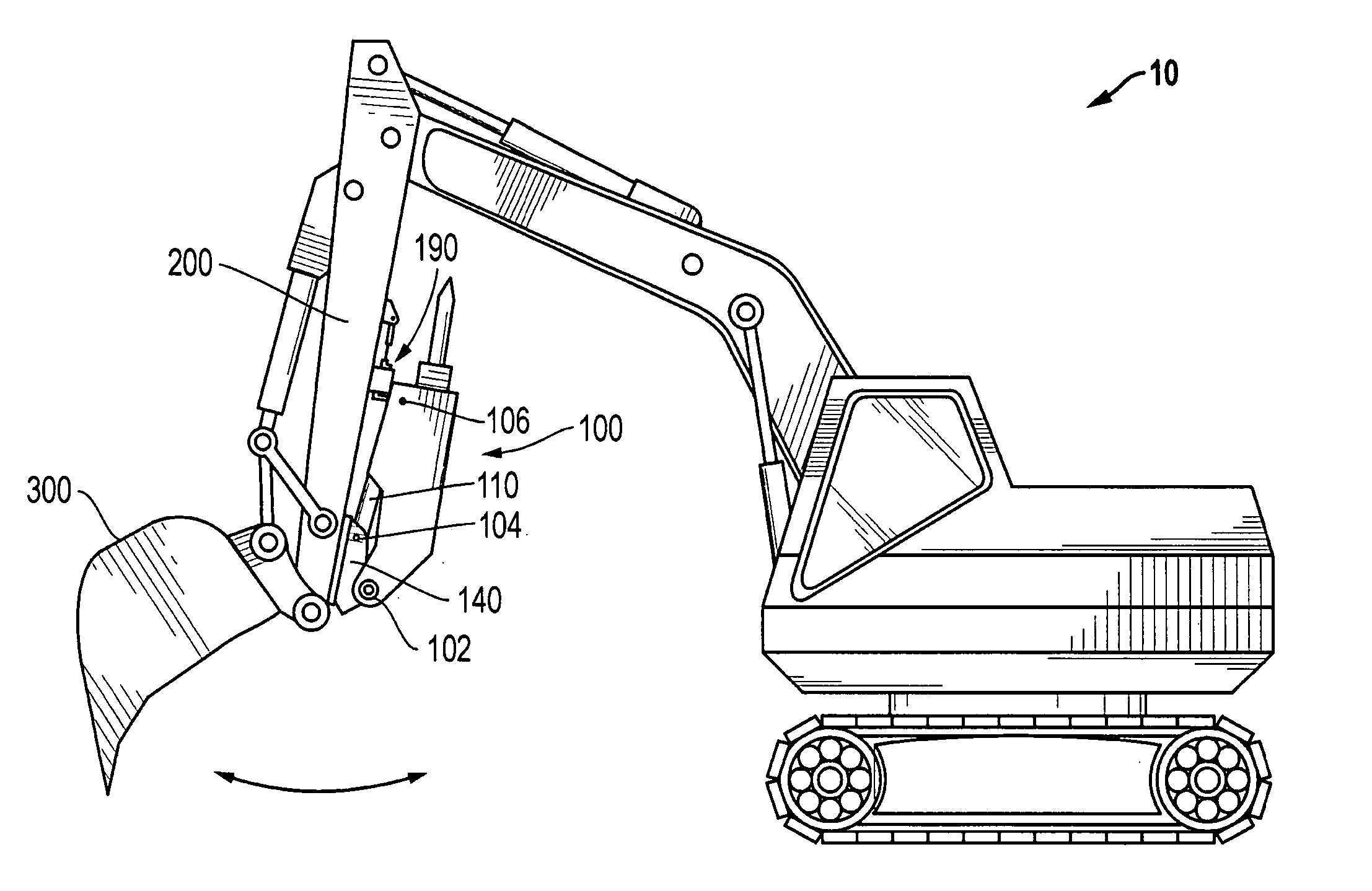
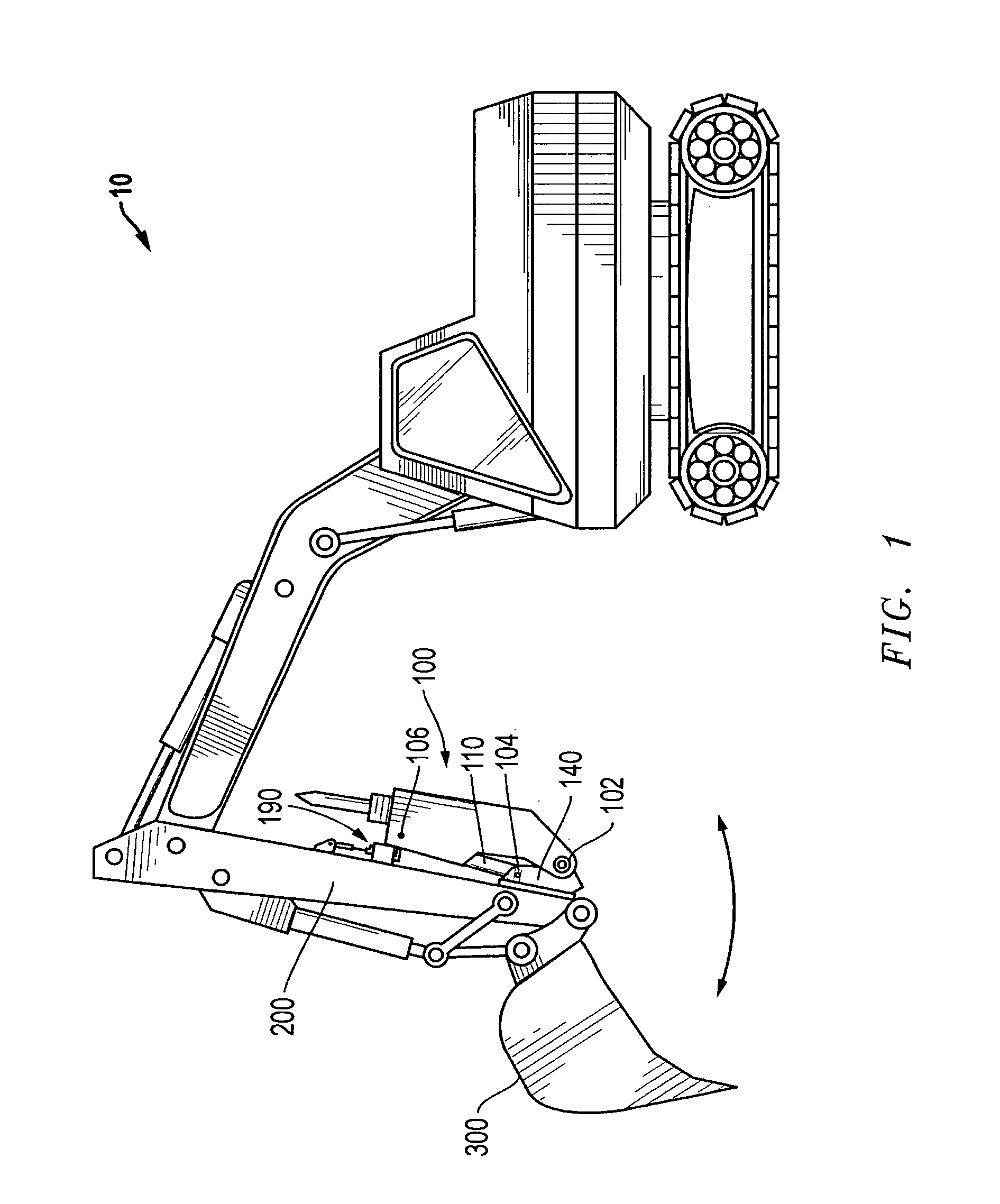
[0038]FIG. 1 discloses earth-excavating machine 10 in accordance with a preferred embodiment of the present invention. A breaker assembly 100 is mounted on boom stick 200 in addition to excavating bucket 300. Breaker assembly 100 is an excavating tool pivotally attached to excavating machine 10 at a first pivot 102, a second pivot 104, and a third pivot 106. A bracket 140 is rigidly attached to boom stick 200 by welding or other means of secure attachment. In the preferred embodiment, breaker assembly 100 is pivotally attached to a bifurcated first pivot 102 on bracket 140.

[0039] A single hydraulic cylinder assembly 110 is pivotally attached at one end to second pivot 104 on bracket 140. Hydraulic cylinder assembly 110 is pivotally attached at its other end...


PUM


Abstract

Disclosed is an excavating machine, representatively a tracked excavator, having a boom stick portion on which both an excavating bucket and a hydraulic breaker are mounted for hydraulically driven pivotal movement between first and second limit positions. The bucket may be operated independently of the breaker for digging operations. Similarly, the breaker may be operated independently of the bucket for refusal material-breaking operations. The same excavating machine may now use the bucket and breaker in a rapid and continuous exchange to permit frequent removal of small quantities of broken refuse material with the bucket, exposing the bucket and breaker to fresh refuse material. The excavating machine disclosed incorporates an impact resistant deployment system with bifurcated and lubricated trunnion pivots and an in-line pivot restriction, or stop. The system provides a breaker assembly connection that permits quick installation and removal of the breaker, and significantly greater durability.

Description

CROSS REFERENCE TO RELATED APPLICATION [0001] This application is a continuation-in-part of co-pending U.S. application Ser. No. 10 / 871,898, filed Jun. 18, 2004, which is a continuation-in-part of co-pending U.S. application Ser. No. 10 / 150,057, filed May 17, 2002, now U.S. Pat. No. 6,751,896, which is a continuation-in-part of co-pending U.S. application Ser. No. 09 / 624,099, filed Jul. 24, 2000, now U.S. Pat. No. 6,430,849. This is also a continuation of U.S. application Ser. No. 11 / 362,670, filed Feb. 27, 2006. All applications from which priority is claimed are hereby incorporated by reference.TECHNICAL FIELD OF THE INVENTION [0002] The present invention generally relates to a material handling apparatus and, in a preferred embodiment thereof, more particularly relates to an excavating machine, representatively a tracked excavator, having operatively attached to the stick portion of its boom a specially designed combination bucket and breaker structure which uniquely permits the ...

Claims


Application Information

Patent Timeline
Patent Type & Authority Applications(United States)
IPC IPC(8): E02F3/96
CPCE02F3/425E02F3/963Y10S37/903E02F9/006E02F3/966
Inventor UNDERWOOD, LOWELL
Owner RECS
Why Eureka
Try Eureka