Eureka AIR delivers breakthrough ideas for toughest innovation challenges, trusted by R&D personnel around the world.

Advanced effusion cooling schemes for combustor domes

Inactive Publication Date: 2006-12-07
HONEYWELL INT INC
View PDF15 Cites 61 Cited by
  • Summary
  • Abstract
  • Description
  • Claims
  • Application Information

AI Technical Summary

Problems solved by technology

Gas turbine combustion systems operate in extreme temperature environments, which ultimately limit the service life of the component.
Although the described methods may be used for dome cooling, they require a large amount of cooling air.
Typically, an excess of cooling air will adversely affect primary zone performance, particularly in the case of a rich quench lean (RQL) combustor.
Further, a disproportionate amount of air required for dome cooling reduces the overall air budget required for cooling and performance of other components.
The initial low film effectiveness is because radial effusion requires several rows of effusion holes for the cooling film to develop.
Although the starter film provided by the impingement air is designed to compensate for the initial low film effectiveness at the beginning of the radially directed cooling film, impingement cooling is less efficient than effusion cooling.
Due to the low efficiency of impingement cooling the described method is not suitable for some applications.
Because the heat shield adds weight and manufacturing complexity to the dome, it is unsuitable for some applications.

Method used


Image

  • Advanced effusion cooling schemes for combustor domes
  • Advanced effusion cooling schemes for combustor domes
  • Advanced effusion cooling schemes for combustor domes

Examples


Embodiment Construction

[0025] The following detailed description is of the best currently contemplated modes of carrying out the invention. The description is not to be taken in a limiting sense, but is made merely for the purpose of illustrating the general principles of the invention, since the scope of the invention is best defined by the appended claims.

[0026] Broadly, the present invention provides cooling schemes for combustor domes and methods for cooling the same. Embodiments of the present invention may find beneficial use in many industries including aerospace, automotive, and electricity generation. The present invention may be beneficial in applications including annular combustors, can combustors and can-annular combustors. This invention may be useful in any combustor dome application. The present invention provides a simplified cooling mechanism on a gas turbine combustor while maximizing cooling efficiency.

[0027] Unlike conventional prior art designs, which employ heat shields, louvers a...


PUM


Abstract

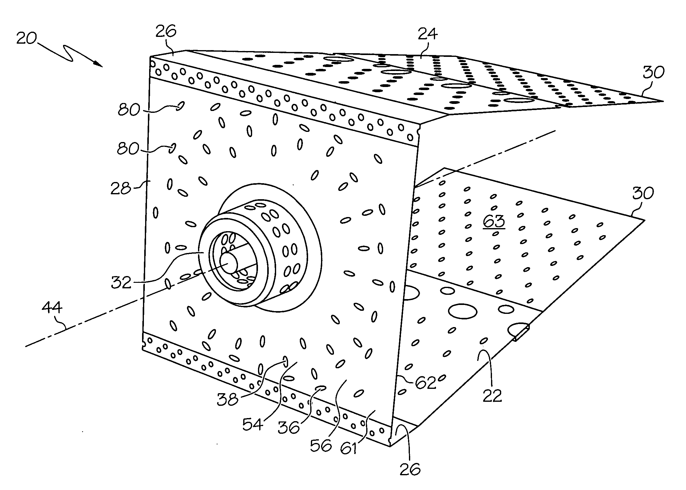
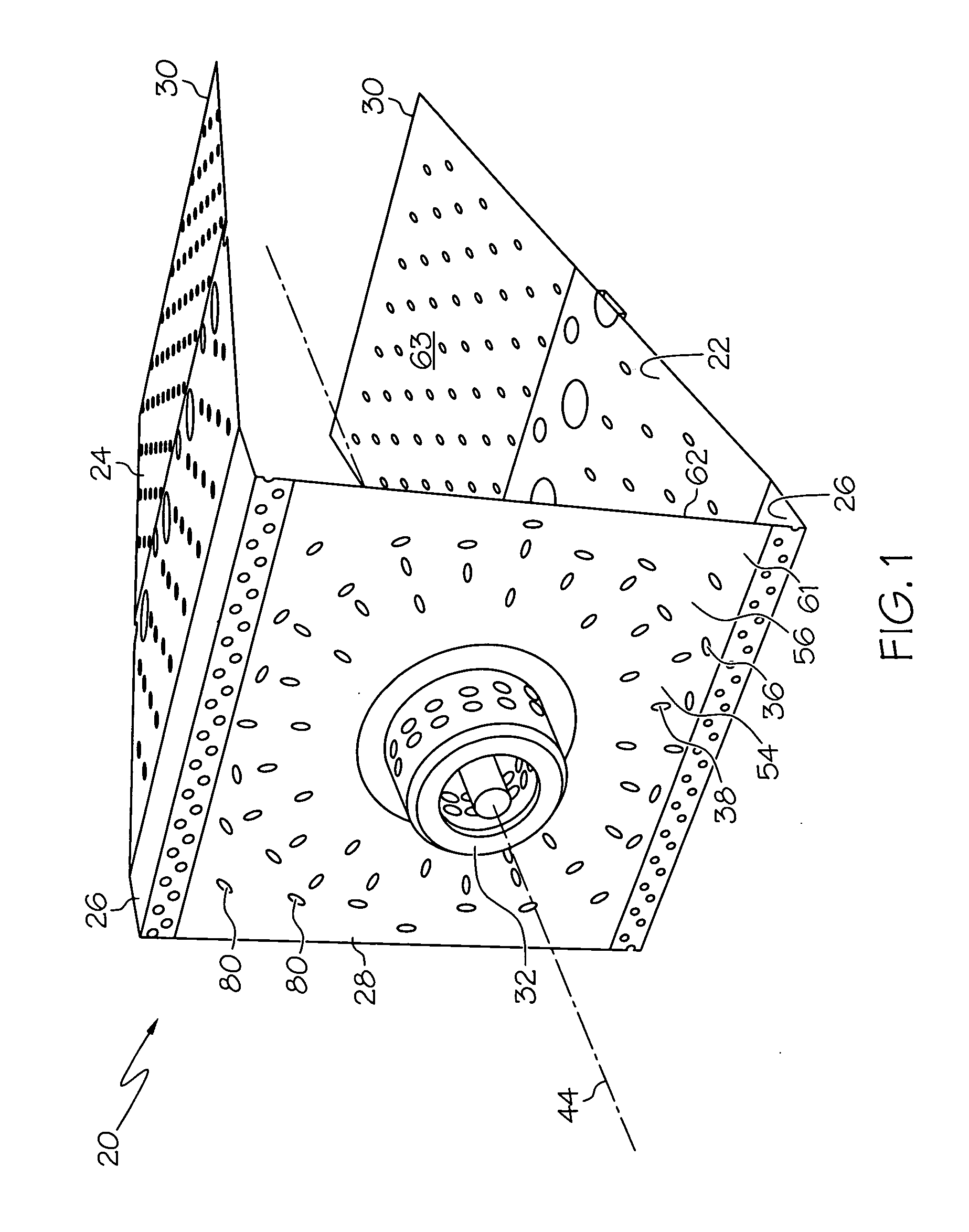
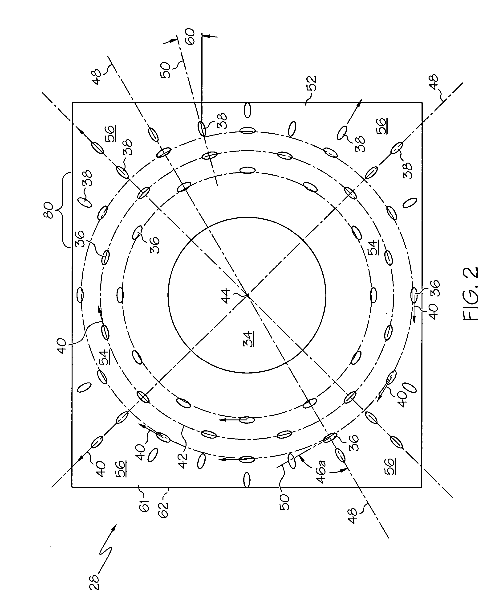
A cooling scheme for a dome comprises an effusion array drilled directly through a single walled dome. In one embodiment, the layout of the holes comprises two regions, a region close to the fuel injector where the holes follow a tangential path around the injector, and a second region where the direction of the holes is radially outward from the injector axis. A film of cooling air may be applied on the interior side of the combustor dome via an air swirler, which projects air radially outward from the injector axis. The first series of cooling holes supplement this air supply so that cooling efficacy is extended along the dome surface and is directed in a counter-rotating manner with respect to the main air swirler. The second series of dome cooling holes infuse further cooling flux that reduces the temperature in the corner regions between fuel injectors.

Description

BACKGROUND OF THE INVENTION [0001] The present invention generally relates to combustors for gas turbine engines and, more particularly, to cooling schemes for combustor domes. [0002] Gas turbine combustion systems operate in extreme temperature environments, which ultimately limit the service life of the component. Cooling techniques are employed to lower the metal temperatures of combustor components to acceptable levels for durability and life. One of the most critical regions requiring cooling is the dome area. [0003] Methods for cooling a combustor dome are described in U.S. Pat. No. 3,705,492. The dome cooling methods described are splash louver type designs whereby air is admitted through relatively large ports in the dome. The air impinges on deflector plates such as to direct the air in a circumferential manner. Although the described methods may be used for dome cooling, they require a large amount of cooling air. Cooling air in the dome region not only plays a part in mit...

Claims


Application Information

Patent Timeline
IPC IPC(8): F23R3/04
CPCF23R3/12Y02T50/675F23R3/50F23R3/10Y02T50/60
Inventor SCHUMACHER, JURGEN C.ZUPANC, FRANK J.DUDEBOUT, RODOLPHE
Owner HONEYWELL INT INC
Why Eureka
Eureka Blog
Learn More