Product dispensing systems

a technology for product dispensing and products, applied in the direction of liquid dispensing, containers, pliable tubular containers, etc., can solve the problems of environmental damage, extreme flammability of nature, and general phase out of propellant gases, and achieve the effect of reducing the chang

Inactive Publication Date: 2006-12-07
KBIG
View PDF7 Cites 14 Cited by
  • Summary
  • Abstract
  • Description
  • Claims
  • Application Information

AI Technical Summary

Benefits of technology

[0091] Working canisters incorporating the product dispense systems of the invention have been made to good effect in terms in particular of initial and final gas pressures during full product dispense as exemplified below with carbon dioxide adsorbed gas in particular: Canister volume300 mlCarbon volume 50 ml‘Free’ canister volume250 mlLiquid product volume225 mlInitial gas pressure 6 baraFinal gas pressure 4 bara (following full product dispense)
[0092] Tests on a canister containing a larger carbonto product volume ratio resulted in a proportionately lower change between initial and final pressures.

Problems solved by technology

However, more recently, such propellant gases have in general been phased out owing to their acknowledged environmentally harmful properties, in particular ozone depletion of the upper atmosphere.
Such gases, however, are by their nature extremely flammable, are environmentally harmful in some respects and in addition can introduce an odour into the product being dispensed.
However such attempts have been largely unsuccessful due to the large pressure changes in the canister during use, commonly leading to reduced dispense characteristics at low pressures and a loss of pressure before full product dispense which results in a slow dispense of the last product from the canister.
In addition, it is known that there has been considerable effort to develop further alternative propellant systems for such product dispense.
However, acetone is an aggressive chemical and it is also known that it was found that the use of acetone in such systems tended to cause problems associated with chemical attack of the membrane material and leakage of the acetone through and around the membrane and resulting failure of the membrane.
As such, the system as a whole is necessarily very complex due in particular to the need to employ the propellant displacing agent during use and provide means to bring it into contact with the solid.

Method used


Image

  • Product dispensing systems
  • Product dispensing systems
  • Product dispensing systems

Examples


Embodiment Construction

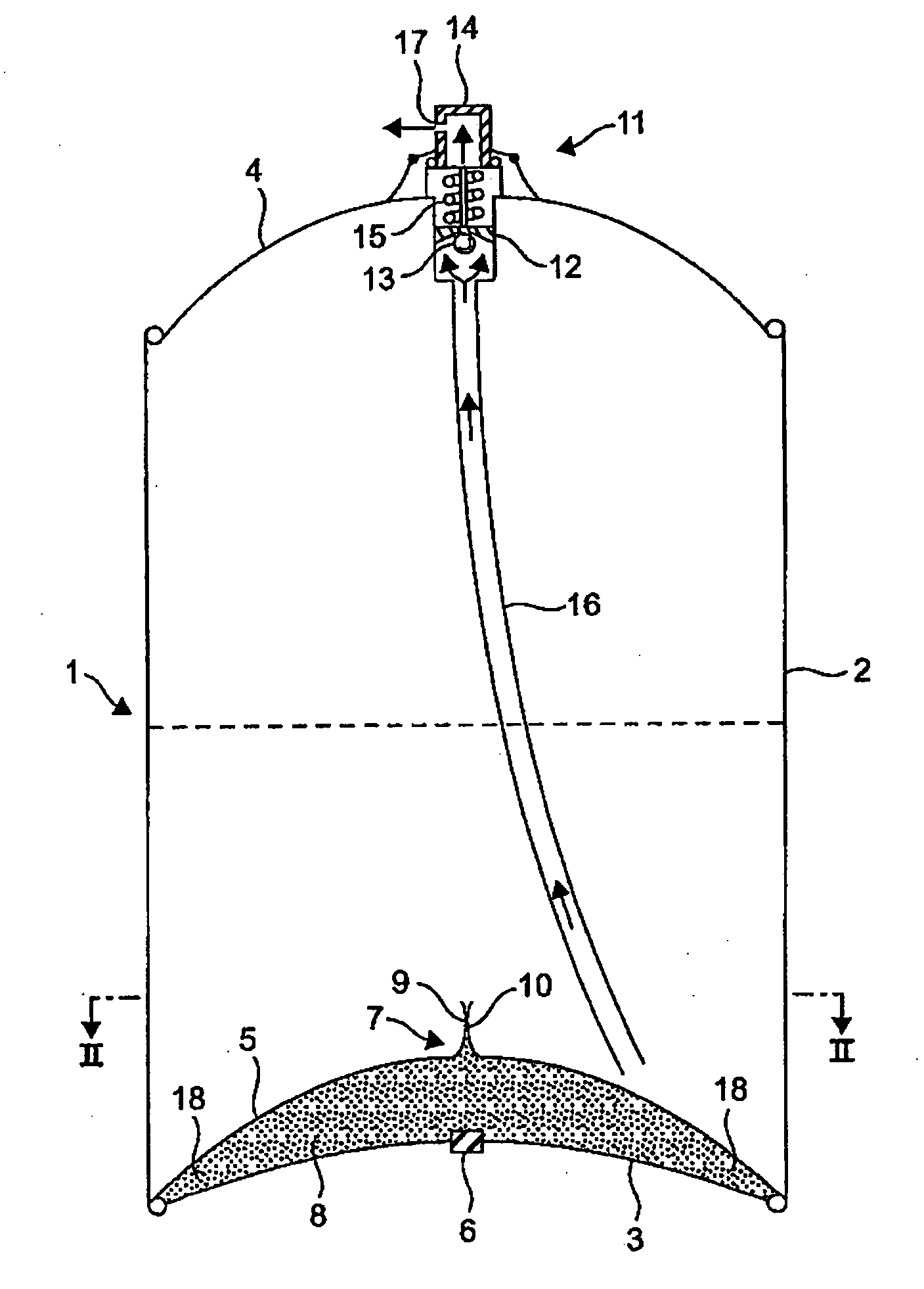
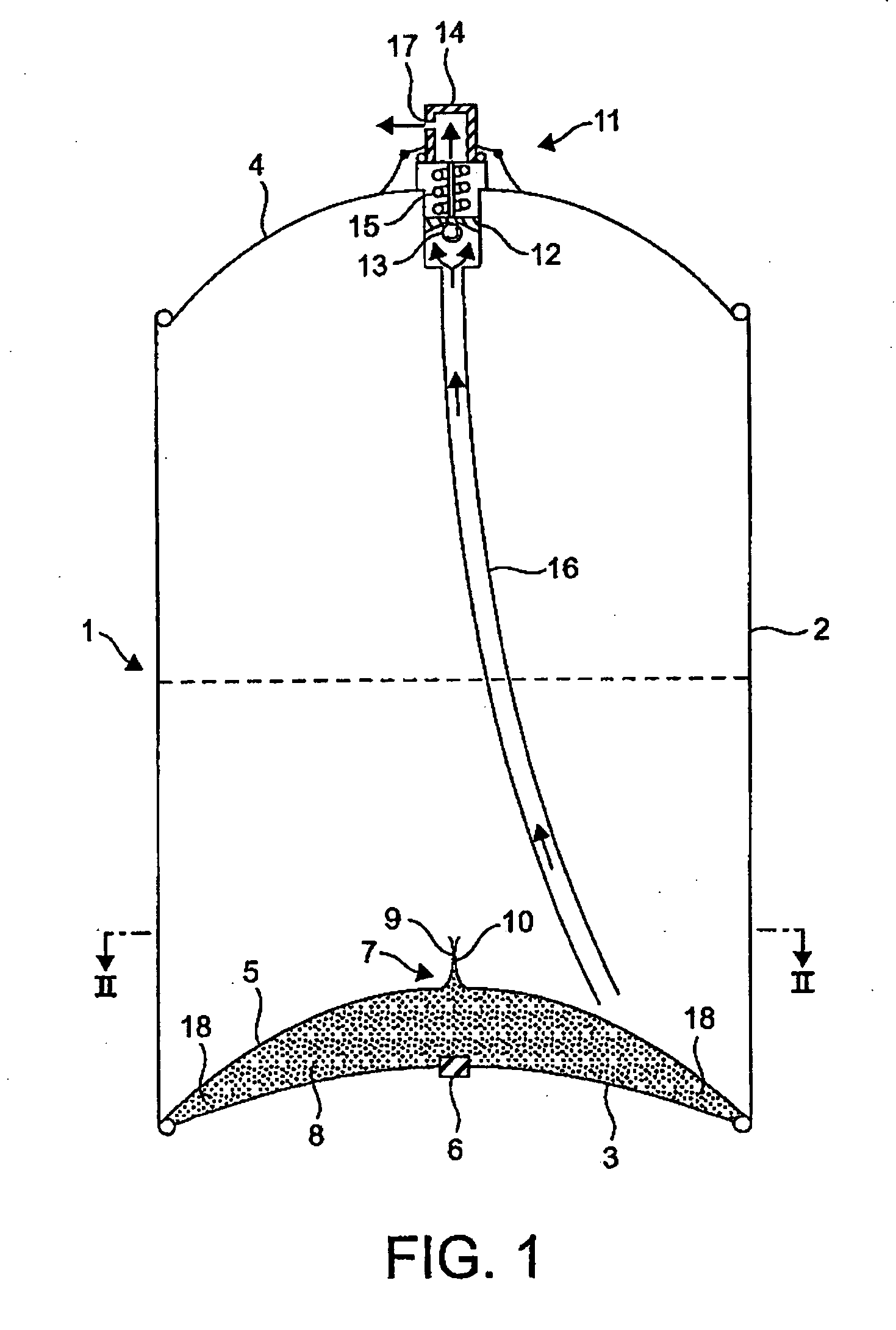
[0099] With reference to the drawings and to FIG. 1 in particular, there is shown a canister 1 incorporating a pressure pack dispensing system of the invention. The canister 1 comprises a cylindrical main body portion 2, a circular base portion 3 of concave shape (external view) and a circular top portion 4 of convex shape (external view), all made of aluminum alloy material.

[0100] The base portion 3 is sealingly crimped around its periphery to the lower edge of the main body portion 2 in a manner known per se for aerosol canister in particular.

[0101] Sandwiched and sealingly held within the crimped structure between the main body portion 2 and the base portion 3 is a circular partition 5 made of plastic and having a greater concavity shape than the base portion 3.

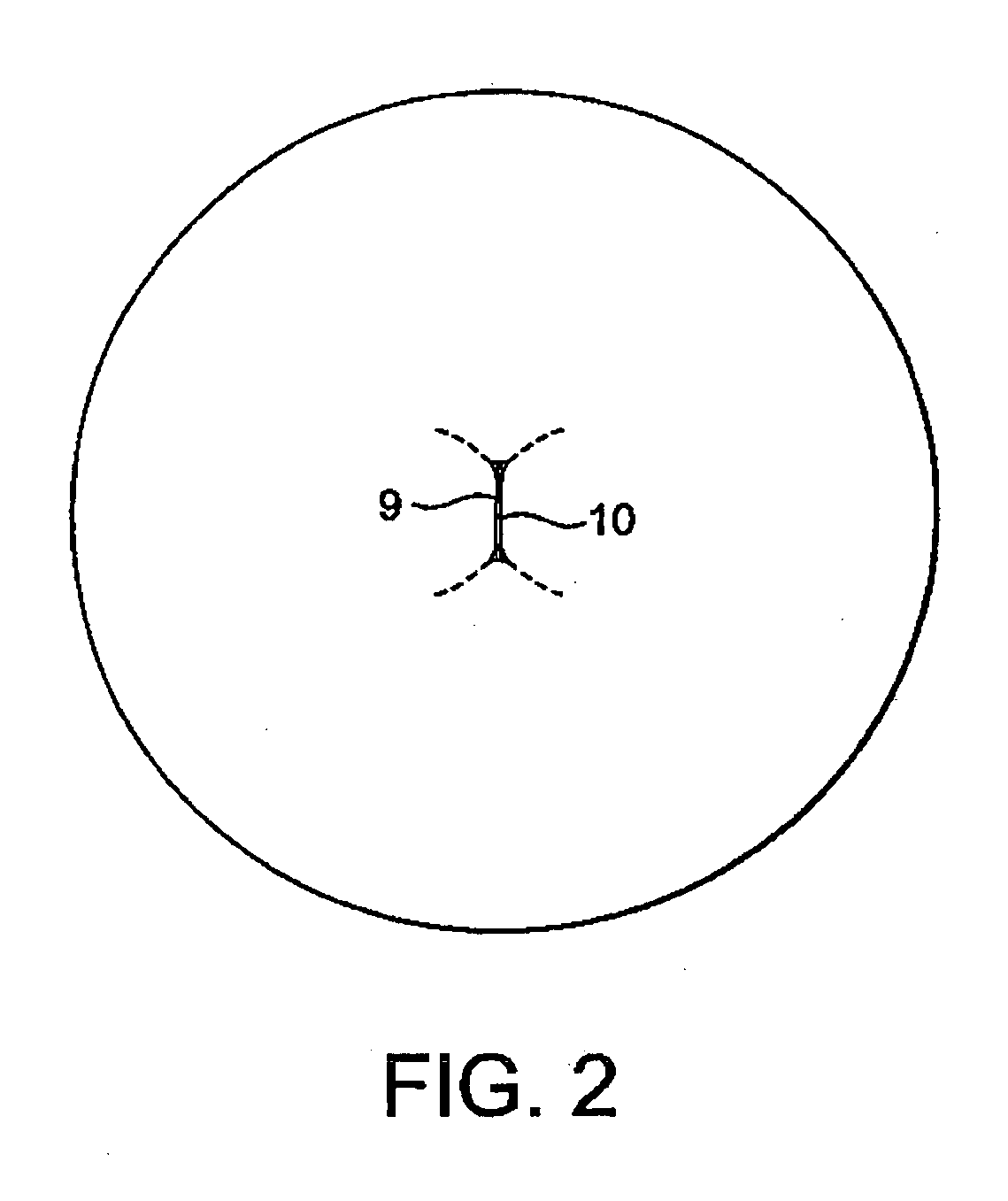
[0102] The base portion 3 has a small circular “bung”6 at its centre made of rubber (or other elastomer) and the partition 5 has an upstanding one-way valve 7 allowing for the flow of fluid from a compartment 8 formed b...


PUM


Abstract

In a dispensing system for dispensing a product form a canister, which comprises a solid/gas arrangement in which the gas is absorbed onto the solid under pressure and desorbed therefrom when the pressure is released and in which the solid comprises activated carbon and the gas comprises one or more of nitrogen, oxygen, (or mixtures thereof including air) carbon dioxide, nitrous oxide and argon, the container has valve means to allow the gas adsorbed onto the carbon to be desorbed and effect product dispense.

Description

[0001] This is a Continuation-In-Part Application of International Application PCT / GB2005 / 000145 filed Jan. 17, 2005 and claiming the priority of GB applications 0401512.9, 0407991.9, 0419135.9, 0419137.9 and 0426490.9 filed Jan. 23, 2004, Apr. 8, 2004, Aug. 27, 2004, Aug. 27, 2004 and respectively, Dec. 2, 2004. BACKGROUND OF THE INVENTION [0002] The present invention relates to systems for dispensing substances from containers and, more particularly, to such systems employing a very simple but effective two phase solid / gas adsorption / desorption mode of operation. [0003] A large number of products are on the general market packaged in canisters—some of which cause the product to be dispensed therefrom in the form of small or atomized particles and are therefore commonly referred to as ‘aerosols’—which can be dispensed from the canister by means of a pressurized gas (or vapor) which is generated in situ in the canister and acts as a dispensing or propellant gas. Such products includ...

Claims


Application Information

Patent Timeline
Patent Type & Authority Applications(United States)
IPC IPC(8): F42B12/46B65D83/14
CPCB65D83/663
Inventor GARRETT, MICHAEL ERNEST
Owner KBIG
Why Eureka
Try Eureka