
Opportunity charging system for battery powered mining equipment

a mining equipment and charging system technology, applied in the direction of charging stations, battery/cell propulsion, transportation and packaging, etc., can solve the problem and achieve the effect of reducing the non-productive time required to change batteries

Inactive Publication Date: 2006-12-07
JOY MM DELAWARE INC
View PDF8 Cites 45 Cited by
  • Summary
  • Abstract
  • Description
  • Claims
  • Application Information

AI Technical Summary

Benefits of technology

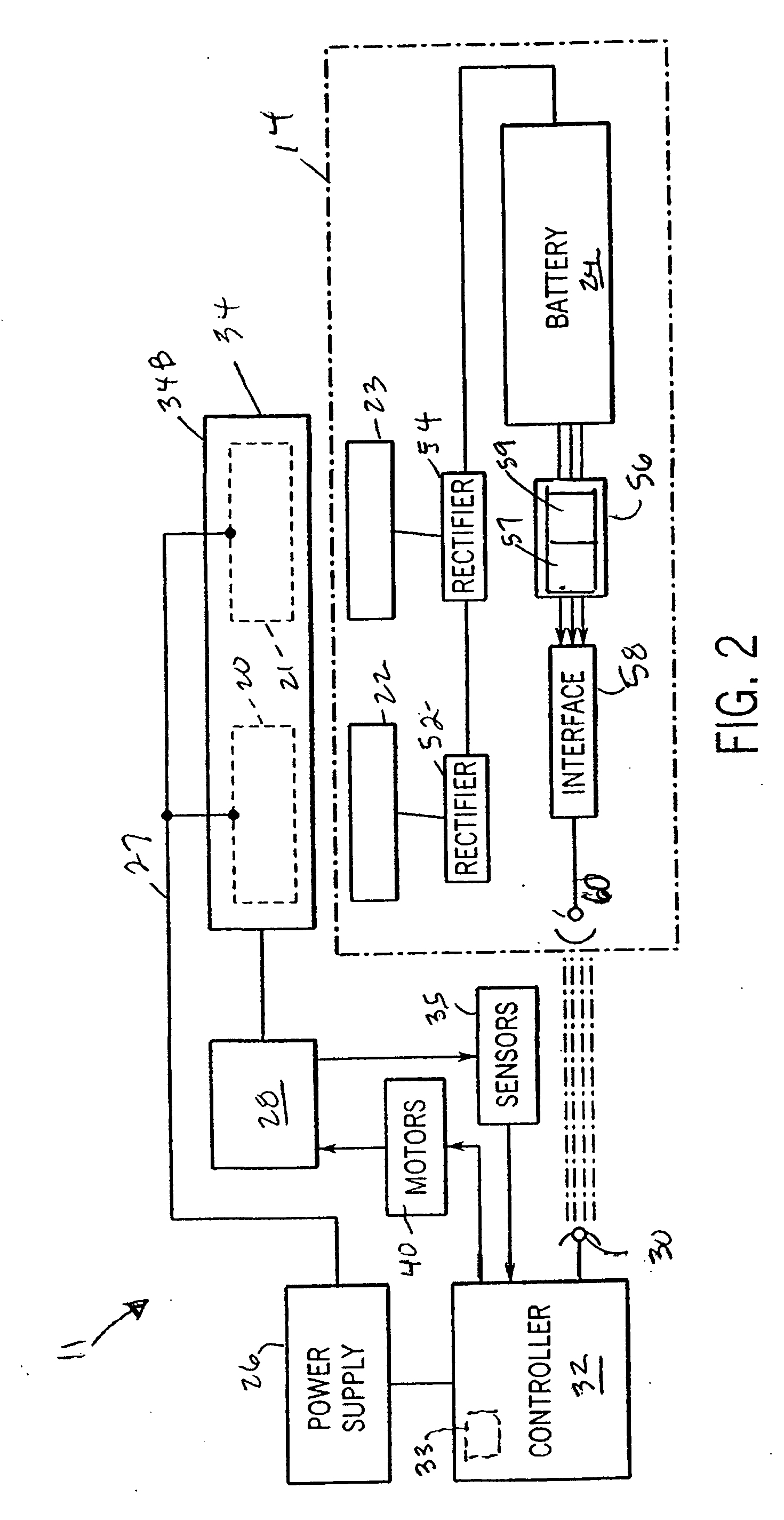
[0012] The disadvantages and limitations of the background art discussed above are overcome by the present invention. With this invention, there is provided an opportunity charging system for providing rapid charging of a battery that provides electric power to move and operate battery powered mobile mining machines. The opportunity charging system allows the storage battery of a mobile mining machine to be recharged without removing the battery from the mobile mining machine and reduces the non-productive time required to change batteries. By way of example, the power transfer components of the opportunity charging system can provide battery charging times as low as twenty seconds.
[0016] This invention provides a means to charge the storage battery on the mobile mining machine, while the mobile mining machine is in operation. The mobile mining machine does not have to be turned off. The mobile mining machine does not have to leave the production area of the section being mined and the operator does not have to leave his operating position on the mobile mining machine.
[0017] The reduced charging time allows increased production time which will result in a reduced cost per ton to mined product, making the mining operation more profitable.
[0018] Moreover, this invention eliminates shortcomings of the prior art battery charging arrangements for mobile mining equipment because the battery remains on the mobile mining machine, and there are no plugs or cables to disconnect, move and reconnect. The present invention keeps the battery in service, on the mobile mining machine at all times. This also makes the job of the operator of the mobile mining machine easier, more productive and safer. In accordance with the present invention, the opportunity charging system can employ at least three batteries for each mobile mining machine. One battery is used for in-service duty, one battery is used for charging and the third battery is used to allow for cool down following charging.
[0020] It may therefore be seen that the present invention provides an opportunity charging system for battery-powered mobile mining machines that is fully automated and which minimizes the amount of time required for maintaining battery in a charged condition. The storage battery on the mobile mining machine is charged while the mobile mining machine is in operation. The mobile mining machine does not have to be turned off and the mobile mining machine does not have to leave the production area of the section being mined.
[0021] The opportunity charging system of the present invention employs apparatus of a construction which is both durable and long lasting, and which will require little or no maintenance to be provided by the user throughout its operating lifetime. The system of the present invention is also inexpensive to implement to enhance its market appeal, thereby affording it the broadest possible market. Finally, all of the aforesaid advantages and objectives are achieved without incurring any substantial relative disadvantage.

Problems solved by technology

The opportunity charging system allows the storage battery of a mobile mining machine to be recharged without removing the battery from the mobile mining machine and reduces the non-productive time required to change batteries.

Method used


Image

  • Opportunity charging system for battery powered mining equipment
  • Opportunity charging system for battery powered mining equipment
  • Opportunity charging system for battery powered mining equipment

Examples


Embodiment Construction

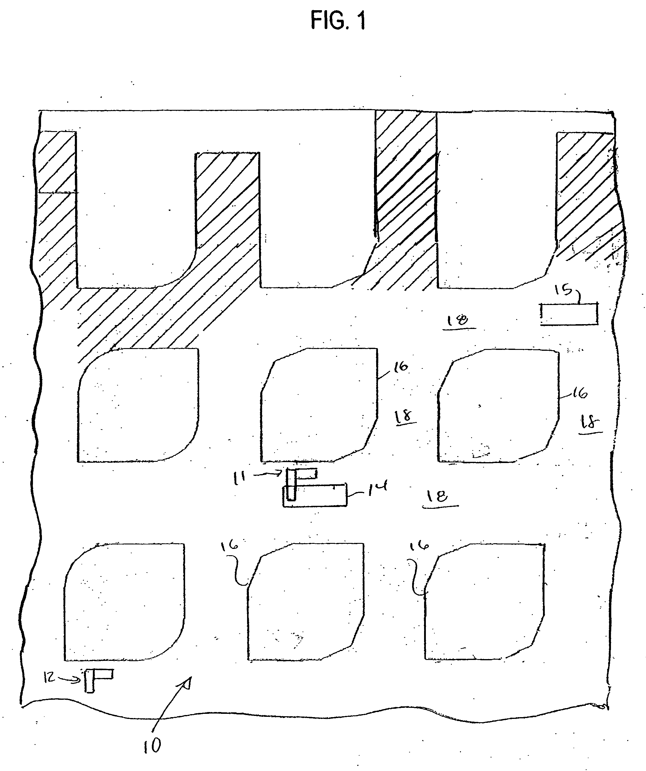
[0032] Referring to FIG. 1, the opportunity battery charging system provided by the present invention is described with reference to an application in a mining operation in a underground mine 10. One or more rapid charging stations, such as rapid charging stations 11 and 12, are provided within the mine for allowing opportunity charging of batteries of a plurality of battery-powered mobile mining machines, such as mobile mining machines 14 and 15, operating within the underground mine. Typically such mobile mining machines are loaded with material removed from mine faces at a location that is close to where the mine is being worked, and the mobile mining machines are driven to a discharge location where the load is discharged onto a conveyor, or other transport mechanism, for carrying the mined material out of the mine.

[0033] For purposes of illustration of the invention, the opportunity battery charging system provided by the present invention is described with reference to an app...


PUM


Abstract

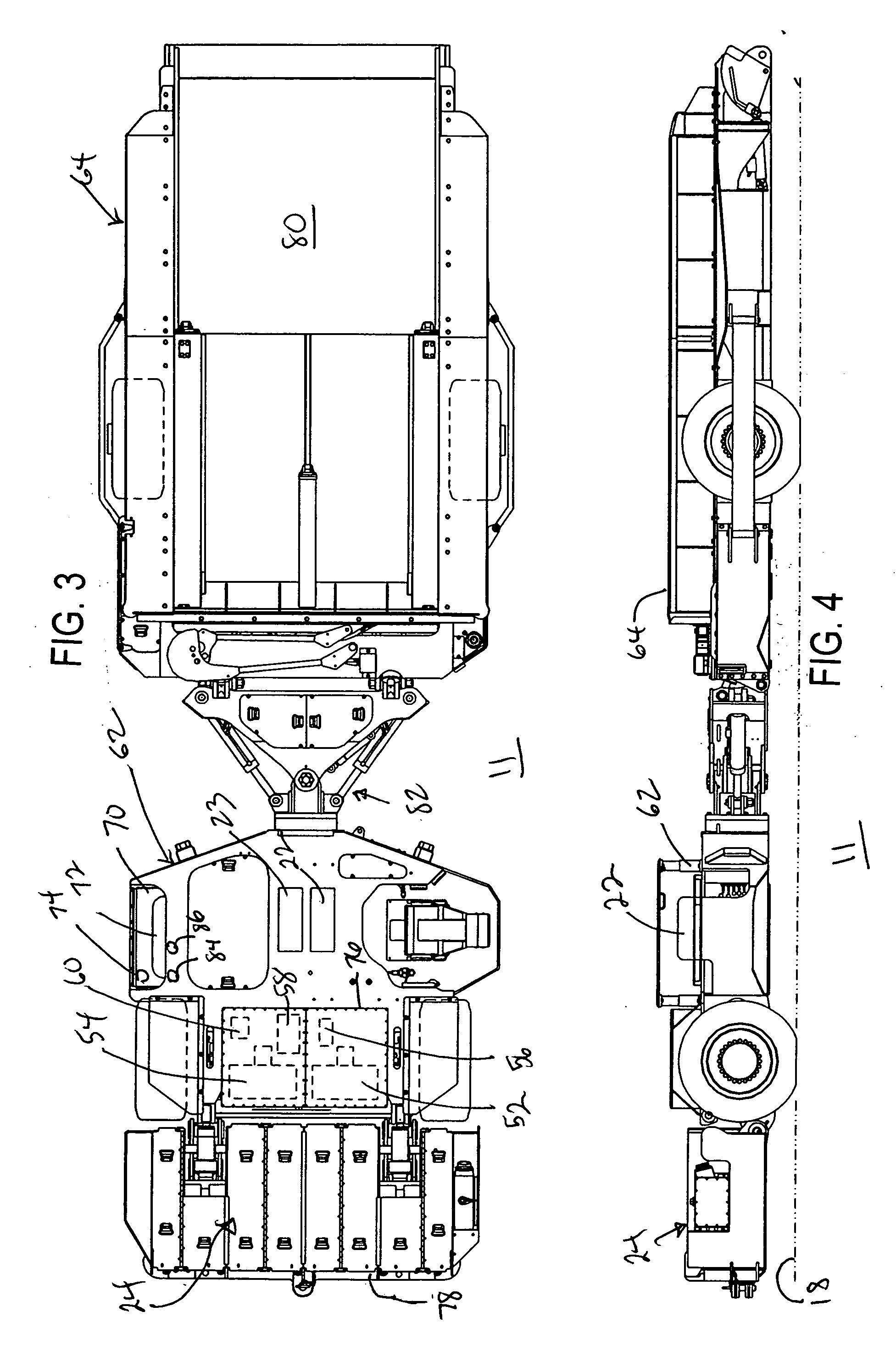
An opportunity charging system for a battery-powered, mobile mining machine employs inductive power transfer for transferring battery charging current produced by a rapid charging station to the battery of the machine. An alignment module of the charging station automatically aligns primary coils of the charging station with pick-up coils carried by the machine in response to detection of the presence of the machine at the charging station. The charging station is located along roadways of the mine normally traveled by production equipment.

Description

BACKGROUND OF THE INVENTION Field of the Invention [0001] The present invention relates generally to battery-powered mobile mining machines used in mining operations, and more particularly, to an opportunity charging system for charging the battery of a mobile mining machine “on the fly”. [0002] Battery-powered mobile mining machines are commonly employed in underground mining operations. After a period of use, the battery on the mobile mining machine becomes drained of energy and must be replaced with a charged battery. Existing technology in the industry is to have a battery charging station in an area of the mine located away from the roadways normally traveled by the production equipment. At the charging station, the discharged battery must be removed from the mobile mining machine and connected to a battery charger. This is accomplished by special design, hydraulically operated apparatus on the mobile mining machine or by use of a forklift or scoop type mobile machine that is o...

Claims


Application Information

Patent Timeline
Patent Type & Authority Applications(United States)
IPC IPC(8): H02J7/00
CPCH02J7/0004Y02T90/121Y02T90/122Y02T10/7088Y02T10/7005Y02T10/705Y02T90/125Y02T90/163Y02T90/169Y02T90/14Y02T90/128Y04S30/14B60L1/003B60L11/182B60L11/1824B60L11/1829B60L11/1848B60L11/185B60L11/1877B60L2200/40B60L2230/16B60L2240/545B60L2240/547B60L2240/549B60L2250/10B60L2250/16B60L2200/26H02J7/025Y02P90/60B60L53/30B60L53/38B60L53/665B60L53/11B60L50/66B60L53/305H02J7/00036H02J50/10H02J50/90B60L53/68B60L53/126B60L53/67H02J7/00047Y02T10/7072Y02T10/70Y02T90/12Y02T90/167Y02T90/16H02J50/80
Inventor BOWLING, DAVID A.RUDINEC, STEPHEN A.
Owner JOY MM DELAWARE INC
Learn More