Ultra-wideband directional antenna

Inactive Publication Date: 2006-12-07
CORETRONIC
View PDF5 Cites 18 Cited by
  • Summary
  • Abstract
  • Description
  • Claims
  • Application Information

AI Technical Summary

Benefits of technology

[0006] An object of the present invention is to provide an ultra-wideband directional antenna, which poss

Problems solved by technology

However, after the conventional antenna is miniaturized, the antenna frequency bandwidth and radiation efficiency are inevitab

Method used


Image

  • Ultra-wideband directional antenna
  • Ultra-wideband directional antenna
  • Ultra-wideband directional antenna

Examples


Example

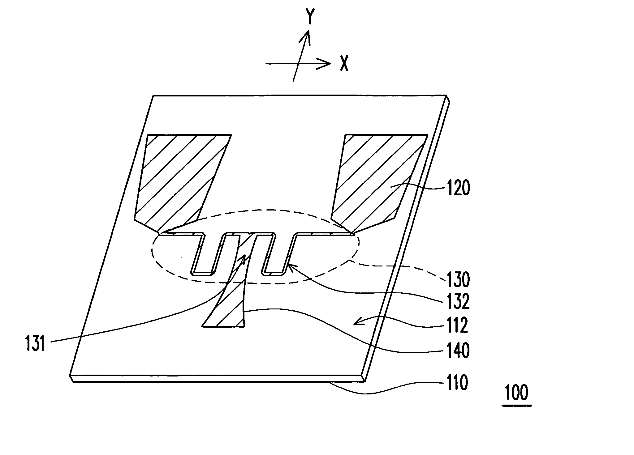
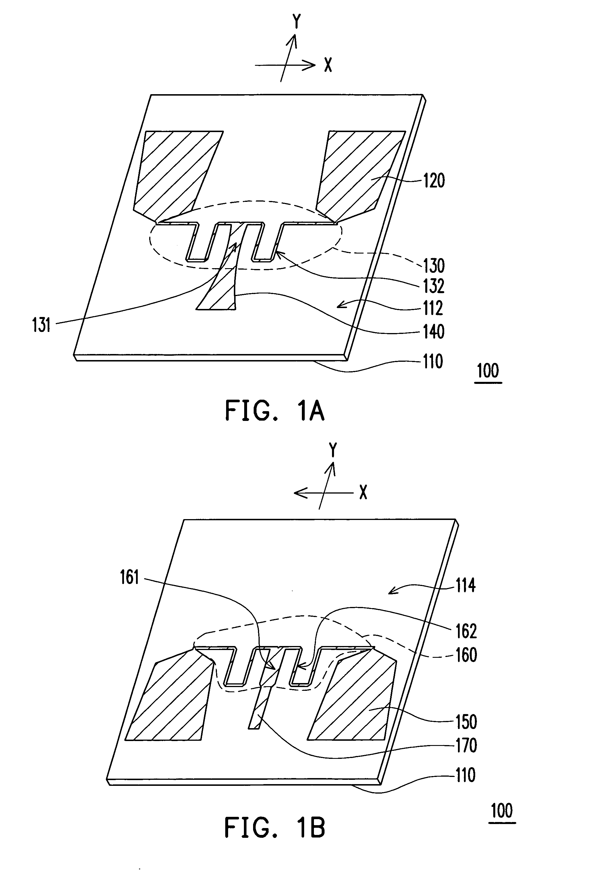
[0012] As shown in FIGS. 1A and 1B, an ultra-wideband directional antenna 100 comprises a dielectric substrate 110, two first antenna elements 120, a first symmetrical microstrip line 130, a first balun 140, two second antenna elements 150, a second symmetrical microstrip line 160, and a second balun 170. The dielectric substrate 110 has a front surface 112 and a back surface 114. Wherein, the dielectric substrate 110 can be a hard substrate used for a print circuit board or other dielectric substrates, such as dielectric substrates composed with glass fiber and epoxy resin. A function of the dielectric substrate 110 is to serve as a loading substrate for antenna patterns, and to electrically insulate the antenna patterns disposed at the front surface 112 and the back surface 114.

[0013] The first antenna elements 120, the first symmetrical microstrip line 130 and the first balun 140 are disposed on the front surface 112 of the dielectric substrate 110. The second antenna elements 1...


PUM


Abstract

An ultra-wideband directional antenna is disclosed, including a dielectric substrate, and antenna elements, symmetrical microstrip lines and baluns on front and back surfaces of the dielectric substrate. Each end of the symmetrical microstrip line is connected to two antenna elements. Wherein, a width of the antenna elements increases gradually outwards from sides of the antenna elements connected to the symmetrical microstrip lines. One end of the balun is connected to the middle segment of the symmetrical microstrip lines, and the other end of the balun is connected to an antenna feeding port. The ultra-wideband directional antenna with thin and compact size has a broadband property with respect to VSWR and a radiation pattern and is suitable for indoor application.

Description

CROSS-REFERENCE TO RELATED APPLICATION [0001] This application claims the priority benefit of Taiwan application serial no. 94118307, filed on Jun. 3, 2005. All disclosure of the Taiwan application is incorporated herein by reference. BACKGROUND OF THE INVENTION [0002] 1. Field of the Invention [0003] This invention generally relates to an antenna, and especially to an ultra-wideband directional antenna. [0004] 2. Description of Related Art [0005] Following a progress of integrated circuit technology in recent years, wireless communication devices have become lighter, thinner and smaller, wherein plane antennas manufactured by a printed circuit method have such advantages as high level of integration and easy integration with periphery elements, and thus have gradually become a mainstream product in recent communication industry. However, after the conventional antenna is miniaturized, the antenna frequency bandwidth and radiation efficiency are inevitably decreased, thus relatively...

Claims


Application Information

Patent Timeline
IPC IPC(8): H01Q9/28H01Q9/16
CPCH01Q1/007H01Q21/062H01Q9/285
Inventor WANG, WEI-JENFU, JO-WANG
Owner CORETRONIC
Why Eureka
Try Eureka