Touch pad with flexible substrate

a flexible substrate and touch pad technology, applied in the field of touch sensor devices, can solve the problems of relative inflexibility of some designs to conform to the limited space available in some applications, the cost of some previous designs, and the inability to meet the needs of some applications, etc., to achieve reliability and flexibility, high temperature resistance, and cost-effective

Active Publication Date: 2006-12-07
SYNAPTICS INC
View PDF4 Cites 176 Cited by
  • Summary
  • Abstract
  • Description
  • Claims
  • Application Information

AI Technical Summary

Benefits of technology

[0007] In one embodiment the touch sensor uses a flexible circuit substrate that provides relatively high temperature resistance. This allows the touch sensor controller to be affixed using reliable techniques, such as various types of thermal bondin

Problems solved by technology

Past designs of touch pads have had several notable limitations.
One limitation has been the relative inflexibility of some designs to conform to the limited spaces available in some applications.
For example, some designs have required large and inflexible circuit boards that prevented the touch pad from being used in small, low profile, or irreg

Method used


Image

  • Touch pad with flexible substrate
  • Touch pad with flexible substrate
  • Touch pad with flexible substrate

Examples


first embodiment

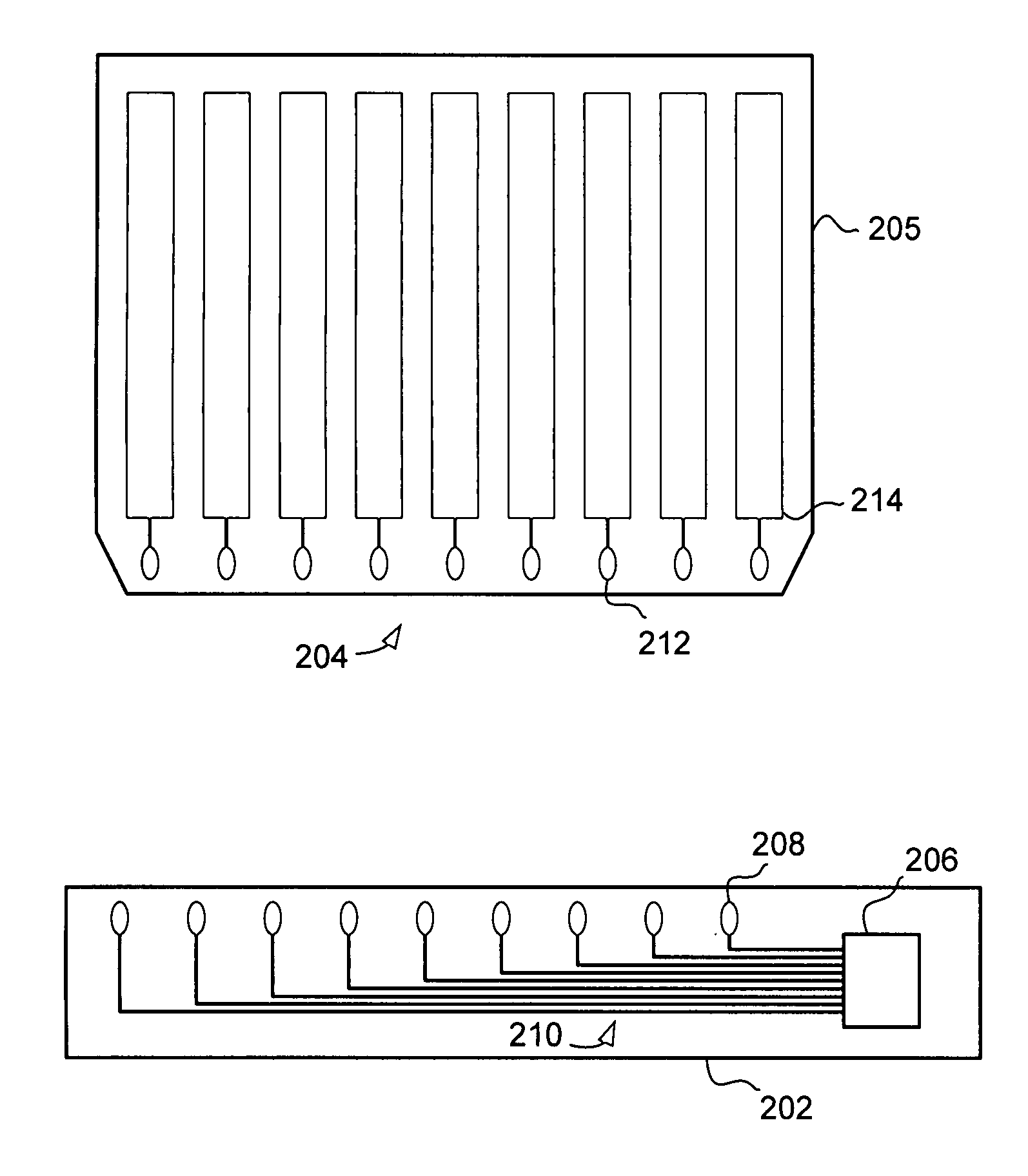
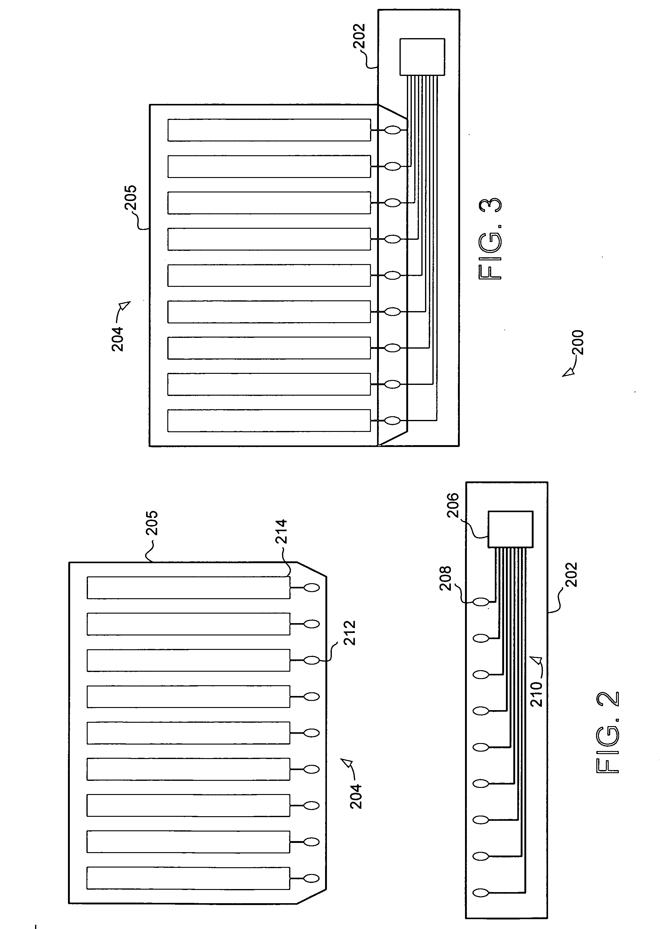
[0026] Turning now to FIGS. 2 and 3, a touch sensor device 200 is illustrated. The touch sensor device 200 includes a flexible circuit substrate 202 and a sensor component 204. FIG. 2 illustrates the flexible circuit substrate 202 and sensor component 204 separately, while FIG. 3 illustrates the substrates coupled together as they may be in a completed touch sensor device.

[0027] In the illustrated embodiment, the flexible circuit substrate 202 includes a touch sensor controller 206, the touch sensor controller 206 coupled to a plurality of pads 208 through a plurality of conductors 210. The sensor component 204 includes a substrate 205 and a plurality of columnar sensing elements 214 for detecting an object proximate to the sensing elements 214. Each of the plurality of sensing elements 214 is coupled to a pad 212. When assembled together and in operation, the touch sensor device 200 detects objects that are proximate to the sensing elements 214, and using the pads 208 and 212, cond...

second embodiment

[0042] Turning now to FIGS. 4 and 5, a touch sensor device 400 is illustrated. The touch sensor device 400 includes a flexible circuit substrate 402 and a sensor component 403. The sensor component 403 includes first sensor substrate 404 and a second sensor substrate 406. FIG. 4 illustrates the flexible circuit substrate 402, first sensor substrate 404 and second sensor substrate 406 separately, while FIG. 5 illustrates the substrates 402, 404 and 406 coupled together as they would be in a completed touch sensor device. In this embodiment the two sensor substrates 404 and 406 each provide object position detection in a different direction. Specifically, each sensor substrate includes a set of sensing elements arranged in a different, nonparallel (e.g., orthogonal) direction. Taken together, the two sensor substrates 404 and 406 provide the ability to detect and precisely locate a proximate object in two dimensions. Alternatively, the two sensor substrates 404 and 406 can also enable...

third embodiment

[0046] Turning now to FIG. 6, a third embodiment touch sensor device 600 is illustrated. In this embodiment the touch sensor 600 includes a flexible circuit substrate 602 and at least one sensor component (not shown in FIG.). This embodiment, like the previous two embodiments uses a flexible circuit substrate with relatively high temperature resistance to provide an improved input device. When combined with relatively low-temperature-resistant sensor components the embodiment can provide significant cost advantages when compared to making the entire touch sensor using high-temperature-resistant material.

[0047] In this embodiment, the flexible circuit substrate 602 includes an integral tail portion 604. The tail portion 604 comprises a relatively narrow strip of flexible circuit substrate with at least one conductor 606 and at least one contact electrode 608 at its end for connection or communication to an electronic system. Because the integral tail portion 604 is made of a flexible...


PUM


Abstract

A touch sensor device is provided that uses a flexible circuit substrate to provide an improved input device. Specifically, the present invention uses a touch sensor controller affixed to the flexible circuit substrate, which is coupled to a sensor component to provide a flexible, reliable and cost effective touch sensor suitable for a wide variety of applications. In one embodiment the touch sensor uses a flexible circuit substrate that provides relatively high temperature resistance. This allows the touch sensor controller to be affixed using reliable techniques, such as various types of soldering. The sensor component can comprise a relatively low-temperature-resistant substrate that can provide a cost effective solution. Taken together, this embodiment of the touch sensor provides reliability and flexibility at relatively low cost.

Description

FIELD OF THE INVENTION [0001] This invention generally relates to electronic devices, and more specifically relates to touch sensor devices. BACKGROUND OF THE INVENTION [0002] Touch sensor devices (also commonly called touch pads) are widely used in a variety of electronic systems. A touch sensor device is typically a sensitive surface that uses capacitive, resistive, inductive, optical, acoustic or other technology to determine the presence, location and or motion of one or more fingers, styli, and / or other objects. The touch sensor device, together with a finger or other object provides an input to the electronic system. For example, touch sensor devices are used as input devices for computers, such as notebook computers. [0003] Touch sensor devices are also used in smaller devices, such as personal digital assistants (PDAs) and communication devices such as wireless telephones and text messaging devices. Increasingly, touch sensor devices are used in multimedia devices, such as C...

Claims


Application Information

Patent Timeline
IPC IPC(8): G09G5/00
CPCH03K17/962G06F3/0414G06F3/03547H05K1/0201H05K2201/10151G06F3/044H05K1/0274G06F3/0412H05K1/189G06F3/04164G06F3/0443G06F3/0446G06F2203/04107H03K2217/960765G06F2203/04102H05K1/0218H05K1/144H05K2201/041H05K2201/10128
Inventor REYNOLDS, JOSEPH KURTHDAY, SHAWN P.
Owner SYNAPTICS INC
Why Eureka
Try Eureka