Liquid crystal display device and electronic apparatus

a liquid crystal display device and display device technology, applied in the direction of instruments, chemistry apparatus and processes, bituminous layered products, etc., can solve the problems of significant color purity imbalance, deterioration of the display quality of the reflective mode of the transflective color liquid crystal display device, and deterioration of the display quality of the transflective mode. , to achieve the effect of improving the brightness of the transmissive display, maintaining enough transmittance ratio without deteriorating color balan

Active Publication Date: 2006-12-07
BOE TECH GRP CO LTD
View PDF8 Cites 38 Cited by
  • Summary
  • Abstract
  • Description
  • Claims
  • Application Information

AI Technical Summary

Benefits of technology

[0029] As mentioned above, since the green light has higher luminosity than that of the red or blue light, it is possible to maintain enough transmittance ratio without deteriorating color balance even if the area of the transmissive region in the green sub-pixel region is set to be smaller than the area of the transmitted region in the red or blue sub-pixel region.
[0030] The reflection layer may be made of a metal film, the reflection layer may be constituted of a reflection polarization layer obtained by making minute slits in a metal film. In particular, when the reflection layer is made of th

Problems solved by technology

However, imbalance in color purity is significant when images are displayed in the reflective mode.
The imbalance in color purity is generated in a display region of one product or in a plurality of products and, in particular, deteriorates the display quality of the reflective mode in the transflective color liquid crystal display device.
As described above, the liquid crystal display dev

Method used


Image

  • Liquid crystal display device and electronic apparatus
  • Liquid crystal display device and electronic apparatus
  • Liquid crystal display device and electronic apparatus

Examples


Embodiment Construction

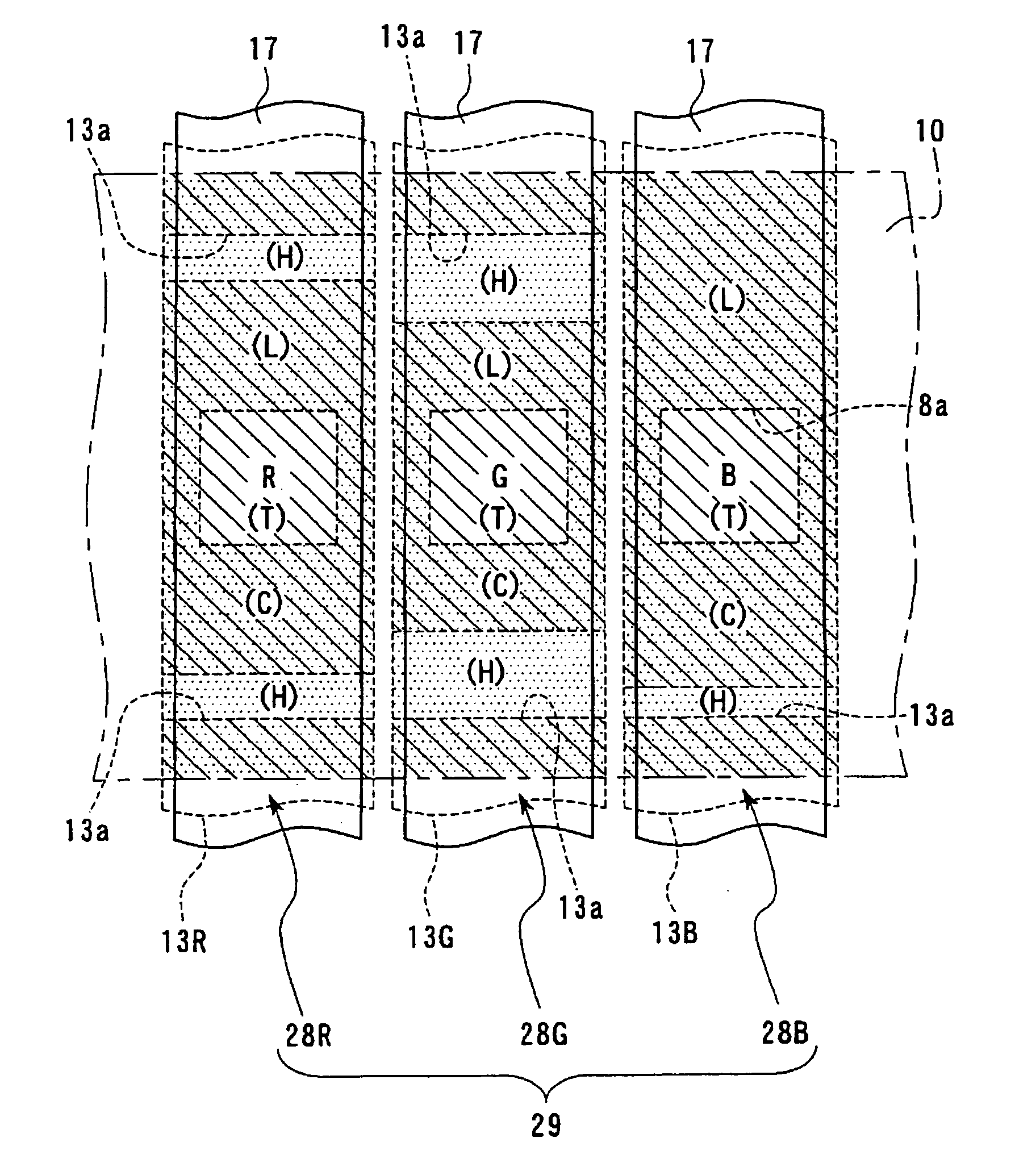
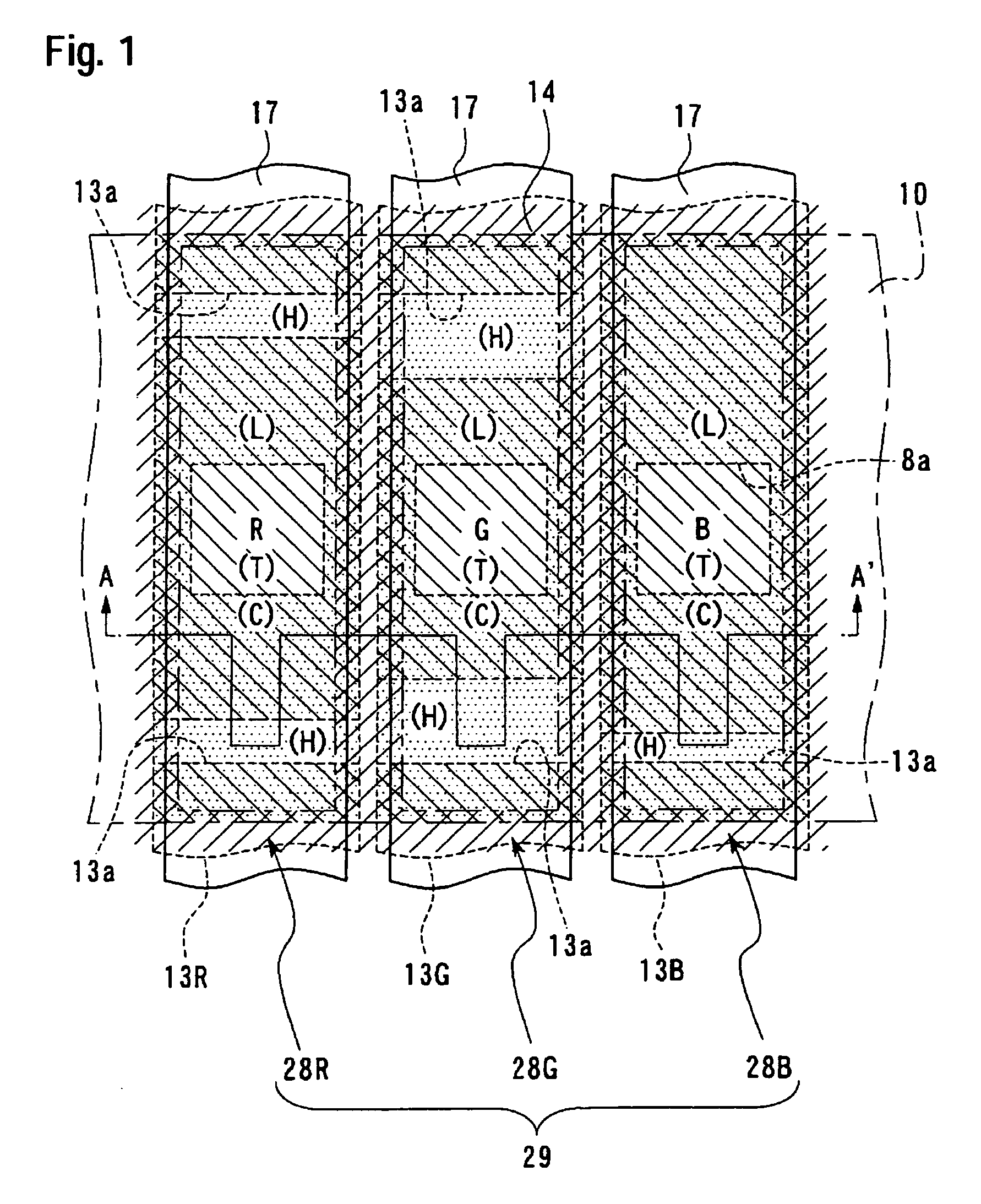
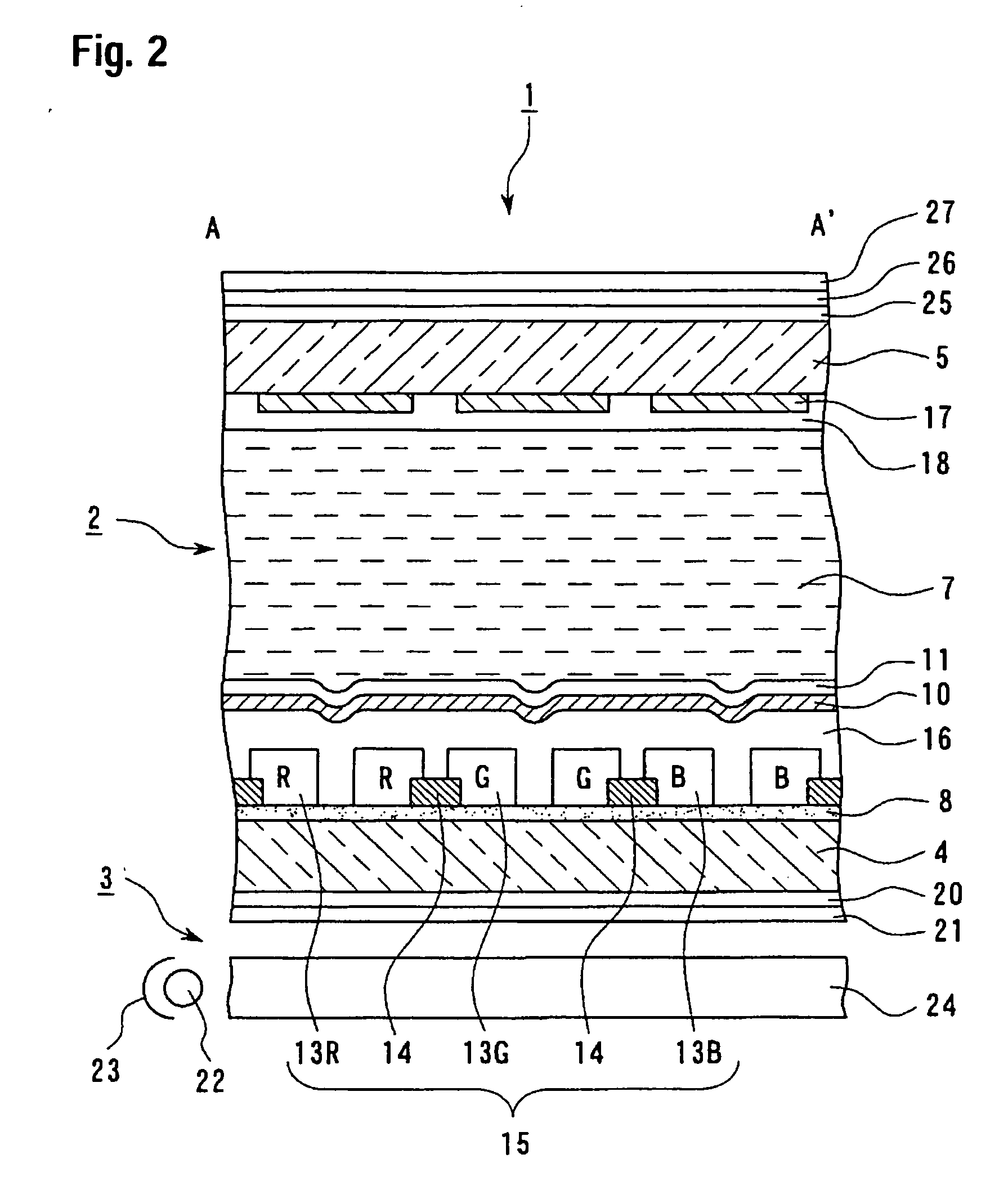
[0044] A first embodiment of the present invention will now be described with reference to FIGS. 1 and 2. A liquid crystal display device according to the present embodiment is an example of a transflective color liquid crystal display device in passive matrices. FIG. 1 is a plan view enlarging a pixel that constructs a display region of the liquid crystal display device according to the present embodiment. FIG. 2 is a sectional view taken along the line A-A′ of FIG. 1. In the drawings, ratio of the thickness of layers and the sizes of the respective components are varied to be recognizable.

[0045] As illustrated in FIG. 2, the liquid crystal display device 1 according to the present embodiment can include a liquid crystal cell 2 and a backlight 3 (illuminating device). In the liquid crystal cell 2, a lower substrate 4 and an upper substrate 5 are arranged to face each other through a sealing material (not shown). A liquid crystal layer 7 made of STN (super twisted nematic) liquid c...


PUM

PropertyMeasurementUnit
Coloraaaaaaaaaa

Abstract

The invention provides a liquid crystal display device capable of displaying colors clearly and with high visibility in both a reflective mode and a transmissive mode. The liquid crystal display device according to the invention can be a transflective liquid crystal display device including a reflection layer, color filters in which coloring layers of different colors are arranged corresponding to sub-pixel regions, and light shielding layers for partitioning the adjacent sub-pixel regions, and the transflective liquid crystal display device displays images in reflective regions and transmissive regions. Colored regions, in which the coloring layers of the color filters exist, and non-colored regions, in which the coloring layers do not exist, are provided in the reflective regions. Both the colored regions and the non-colored regions can be provided so as to overlap the light shielding layers along the longitudinal direction of the sub-pixel regions in plan view.

Description

[0001] This is a Division of application Ser. No. 10 / 808,405 filed Mar. 25, 2004, which in turn claims priority from Japanese Patent Application No. 2003-116365, filed Apr. 21, 2003. The entire disclosures of the prior applications are hereby incorporated by reference herein in their entirety.BACKGROUND OF THE INVENTION [0002] 1. Technical Field of Invention [0003] The invention relates to liquid crystal display devices and electronic apparatuses. More particularly, the invention relates to the structure of a transflective liquid crystal display device in which color purity is well balanced both in a transflective mode and a transmissive mode. [0004] 2. Description of Related Art [0005] Liquid crystal display devices capable of displaying images using external light, such as sunlight and artificial illumination in bright places and an internal light source, such as a backlight in dark places are provided. That is, the liquid crystal display devices use a display method that includes...

Claims


Application Information

Patent Timeline
IPC IPC(8): G02F1/1335G02B5/20G02F1/13
CPCG02F1/133555G02F1/133514B32B11/10B32B11/02B32B5/022B32B2307/7265B32B2262/0276
Inventor IIJIMA, CHIYOAKIWADA, HIROSHI
Owner BOE TECH GRP CO LTD
Why Eureka
Try Eureka