Method and apparatus for measuring a polishing condition

a technology of polishing state and monitoring apparatus, which is applied in the direction of lapping machines, instruments, manufacturing tools, etc., can solve the problems of difficult to grasp the polishing state at a specific position of a surface, and the progress of polish cannot be easily confirmed from a characteristic value, so as to facilitate the detection of the progress of polishing of an obj

Active Publication Date: 2006-12-07
EBARA CORP
View PDF15 Cites 55 Cited by
  • Summary
  • Abstract
  • Description
  • Claims
  • Application Information

AI Technical Summary

Benefits of technology

[0007] The present invention has been proposed to solve the problems of the above prior art and the object of the present invention is to provide a polished state monitoring apparatus capable o

Problems solved by technology

However, it is difficult to grasp a polished state at a specific position of a surface to be polished (e.g. wafer center) because characteristic values are changed in each scan operation due to an effect by the above profile.
Moreover, there is a proble

Method used


Image

  • Method and apparatus for measuring a polishing condition
  • Method and apparatus for measuring a polishing condition
  • Method and apparatus for measuring a polishing condition

Examples


Embodiment Construction

[0040] An embodiment of a polished state monitoring apparatus according to the present invention is described below in detail by referring to the accompanying drawings. In the drawings, the same or corresponding components are designated by the same symbols and any double description will be omitted hereafter.

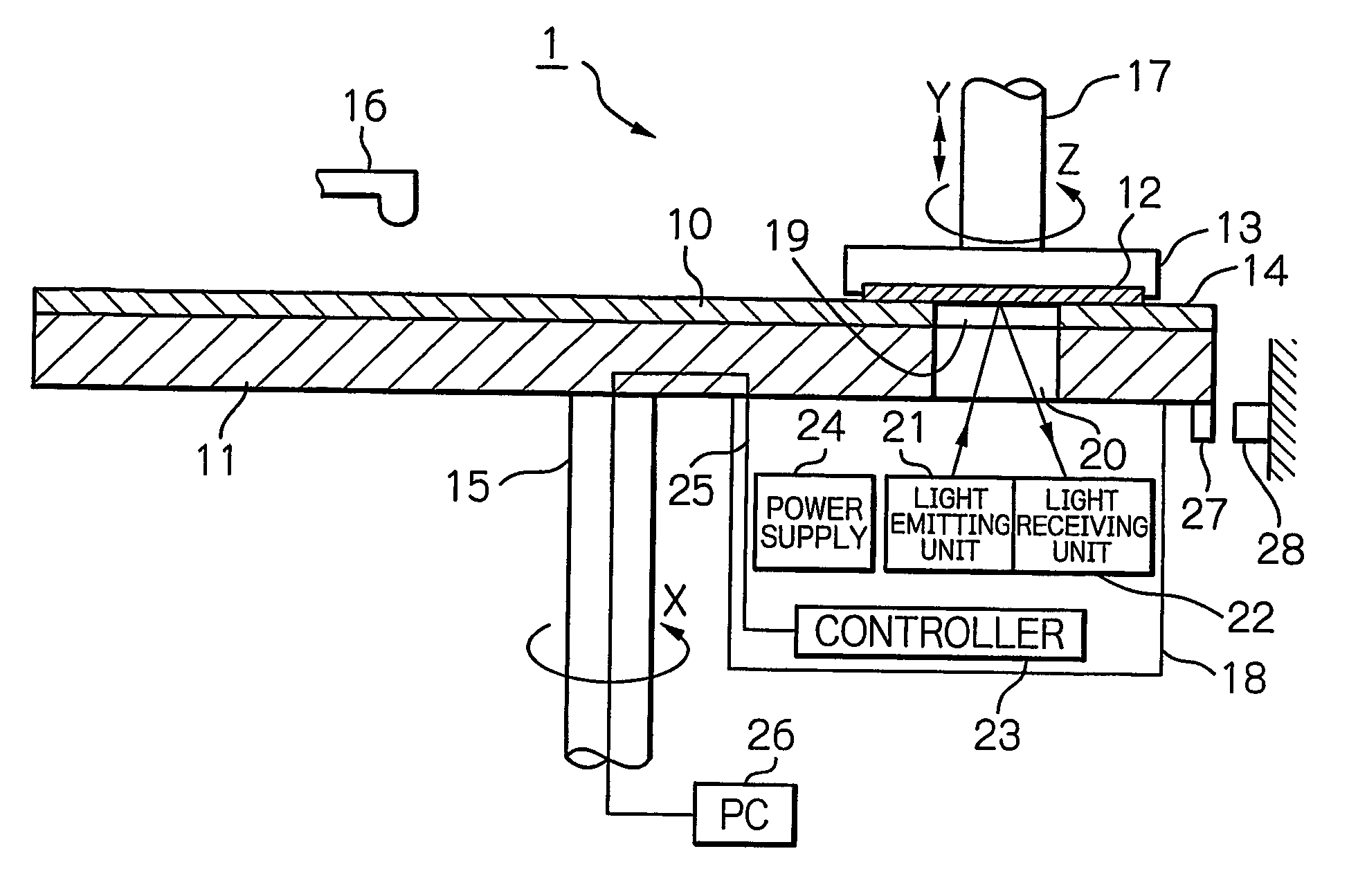
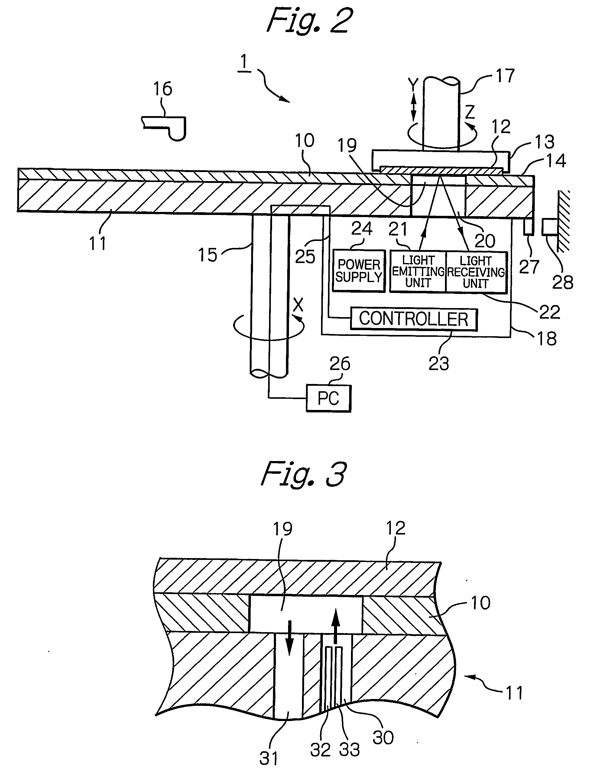
[0041]FIG. 2 is an illustration schematically showing a whole structure of a polishing apparatus having a polished state monitoring apparatus according to the present invention. In FIG. 2, a polishing apparatus 1 has a polishing turntable 11 on one side of which a polishing cloth 10 is affixed, and a top ring 13 for holding a semiconductor wafer 12 to press it against a surface of the polishing cloth 10. The semiconductor wafer 12 is attracted and held by a lower surface of the top ring 13. A surface 14 of the polishing cloth 10 facing the semiconductor wafer 12 is a polishing surface contacting with the semiconductor wafer 12 with friction. In this case, it is also possible t...


PUM

PropertyMeasurementUnit
Timeaaaaaaaaaa
Distanceaaaaaaaaaa

Abstract

A polished state monitoring apparatus capable of easily grasping the progress of polish is provided. The polished state monitoring apparatus monitors the progress of polish of a surface to be polished by obtaining a characteristic value indicating a state of the polished surface of an object 12 at each sampling point every predetermined interval while scanning the surface. The apparatus comprises light emitting means 21 capable of emitting light for irradiating the surface and computing units 26 for receiving light reflected from the surface to generate a characteristic value. Then, the apparatus fetches the characteristic values obtained from the sampling points at the same sampling timing during each scan and outputs the characteristic values. This enables the progress of the polish to be monitored in accordance with the distance from the center of the surface.

Description

FIELD OF THE INVENTION [0001] The present invention relates to a polished state monitoring apparatus for measuring a characteristic value of a surface to be polished of an object to be polished such as a semiconductor wafer and deciding a timing of the end point of polish, as well as a polishing apparatus having the polishing state monitoring apparatus. BACKGROUND OF THE INVENTION [0002] Chemical mechanical polishing (CMP) is already known which removes irregularity from a surface of a semiconductor wafer to flatten the surface. In the case of chemical mechanical polishing, it is necessary to complete the polish when a film to be polished such as an interlayer insulating film becomes a desired thickness. Moreover, it may be requested to complete polish when a film to be polished is removed and a base stopper film or barrier film appears like the case of STI (shallow trench isolation) or copper wiring film. As means for satisfying these requests, a polished state monitoring apparatus...

Claims


Application Information

Patent Timeline
IPC IPC(8): G01B11/30B24B49/02B24B37/013B24B49/12H01L21/304
CPCB24B49/12B24B37/013B24B37/04B24B49/02H01L21/304
Inventor KOBAYASHI, YOICHIMITANI, RYUICHIRO
Owner EBARA CORP
Why Eureka
Try Eureka