Intravascular cuff

a cuff and artery technology, applied in the field of intravascular cuffs, can solve the problems of reducing the diameter of the lumen, thickening of the valve leaflet, and subsequent immobility or reduction of mobility, and achieve the effect of reducing the diameter lumen

Active Publication Date: 2006-12-07
EDWARDS LIFESCIENCES CORP
View PDF13 Cites 410 Cited by
  • Summary
  • Abstract
  • Description
  • Claims
  • Application Information

AI Technical Summary

Benefits of technology

[0012] The present invention addresses the aforementioned drawbacks by providing a tubular or toroidal cuff that surrounds a native valve and creates an ideal implantation site for a stent. The cuff is constructed of at least one fine braided strand of a material having super-elastic or shape memory characteristics, such as Nitinol. The cuff is tubular when

Problems solved by technology

A number of diseases result in a thickening, and subsequent immobility or reduced mobility, of valve leaflets.
The increased resistance to blood flow that a stenosed valve presents eventually leads to heart failure and death.
Naturally, this is a heavily invasive procedure and inflicts great trauma on the body leading usually to great discomfort and considerable recovery time.
One particular drawback with the percutaneous approach disclosed in the Andersen '614 patent is the difficulty in preventing leakage around the perimeter of the new valve after implantation.
As the tissue of the native valve remains within the lumen, there is a strong likelihood that the commissural junctions and fusion points of the valve tissue (as pushed against the lumen wall) will make sealing of the prosthetic valve around the interface between the lumen and the prosthetic valve difficult.
Other drawbacks of the Andersen '614 approach pertain to its reliance on stents as support scaffolding for the prosthetic valve.
First, stents can create emboli when they expand.
Second, stents are typically not effective at trapping the emboli they dislodge, either during or after deployment.
Third,

Method used


Image

  • Intravascular cuff
  • Intravascular cuff
  • Intravascular cuff

Examples


Embodiment Construction

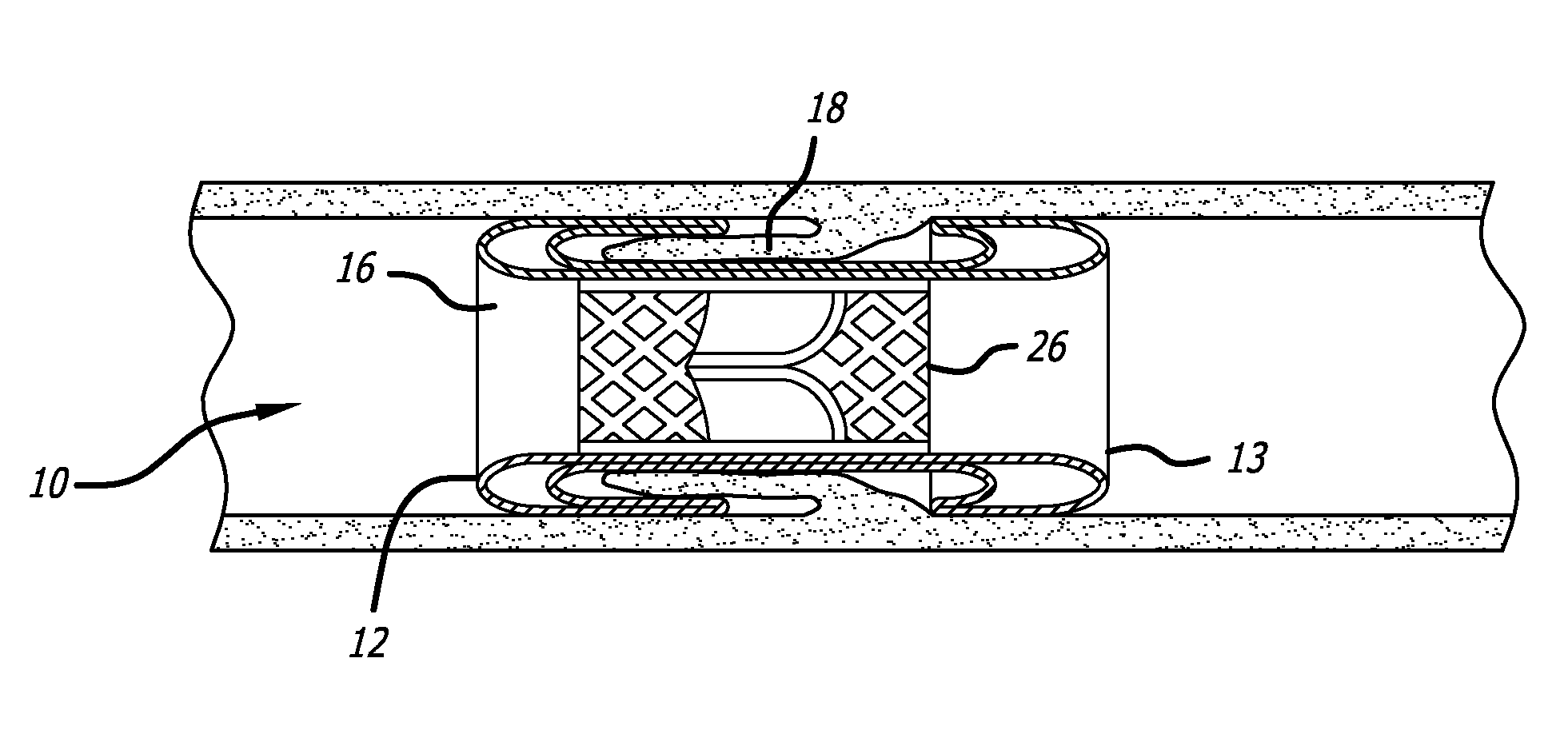
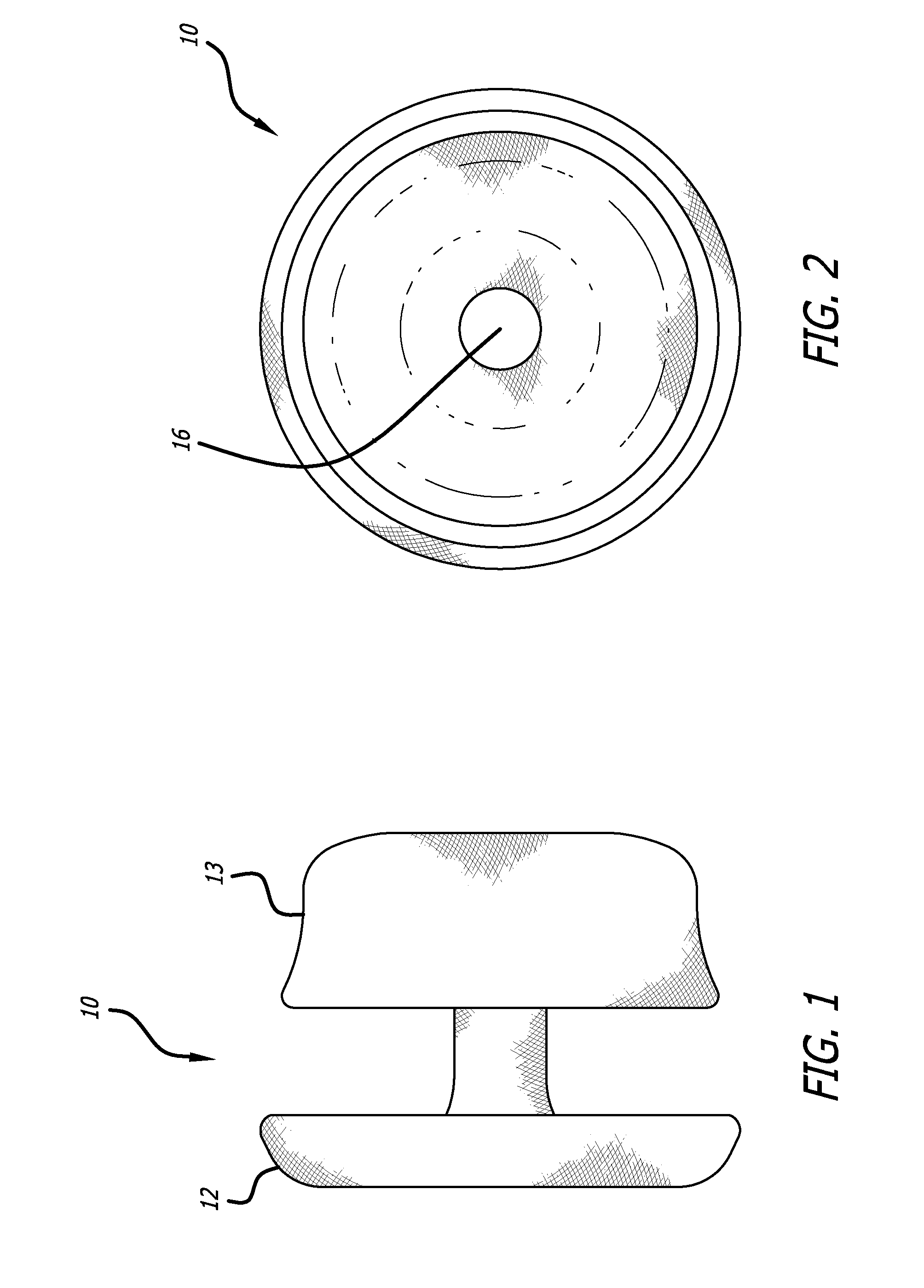
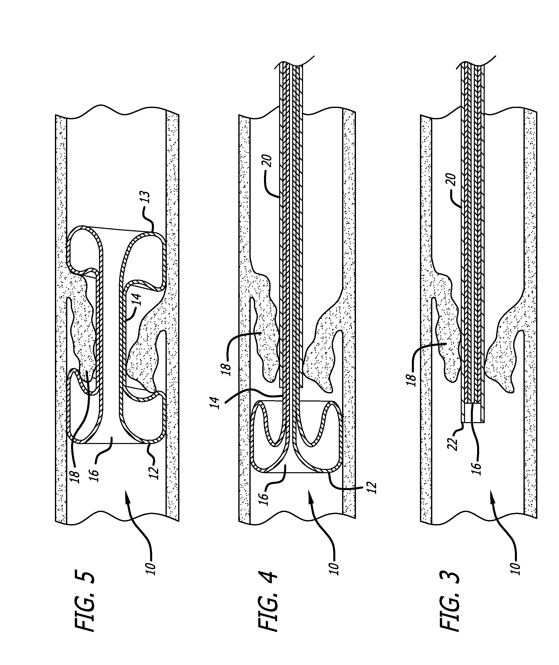
[0019] Referring now to the Figures and first to FIGS. 1 and 2, there is shown an intravascular cuff 10 of the present invention. The cuff 10 is shown in its relaxed, expanded configuration and comprises a generally tubular structure having two flared ends 12 and 13 and a narrow tubular body 14. The elongated tube that is used to construct the cuff 10 is formed from at least one braided strand capable of exhibiting super-elasticity or shape memory. In one embodiment, the elongated tube is folded in half upon itself such that the first end 12 becomes a folded end and the second end 13 includes a plurality of unbraided strands. The tubular body is thus two-ply. The strand or strands may be fibrous, non-fibrous, multifilament, or monofilament. Nitinol is an example of a preferable material for the strand(s). The strand(s) are braided to allow the device to be expanded longitudinally into a very long, thin tube capable of being placed in a very small delivery catheter. Preferably, the c...


PUM


Abstract

An intravascular cuff acts as a lining between a native vessel and an intravascular prosthetic device. During deployment, the ends of the cuff curl back upon themselves and are capable of trapping native tissue, such as valve leaflet tissue, between the ends. The cuff creates a seal between the vessel and the prosthetic, thereby preventing leakage around the prosthetic. The cuff also traps any embolic material dislodged from the vessel during expansion of the prosthetic.

Description

CROSS-REFERENCE TO RELATED DOCUMENTS [0001] This application is related to and claims priority benefit of U.S. Provisional Patent Application Ser. No. 60 / 685,433, filed May 27, 2005, entitled Intravascular Cuff, by Wilson et al. and is also hereby incorporated by reference herein. This application also incorporates by reference U.S. patent application Ser. No. ______ entitled Stentless Support Structure filed by Applicant on even date herewith and U.S. Provisional Patent Application Ser. No. 60 / 685,349, filed May 27, 2005, entitled Stentless Support Structure and U.S. Provisional Patent Application Ser. No. 60 / 709,595, filed Aug. 18, 2005, entitled Stentless Support Structure.BACKGROUND OF THE INVENTION [0002] There has been a significant movement toward developing and performing cardiac and other surgeries using a percutaneous approach. Through the use of one or more catheters that are introduced through, for example, the femoral artery, tools and devices can be delivered to a desi...

Claims


Application Information

Patent Timeline
IPC IPC(8): A61F2/06
CPCA61F2/2418A61F2/2475A61F2002/302A61F2002/30604A61F2230/0078A61F2250/0039A61F2250/006A61F2250/0003A61F2230/0065A61F2/07A61F2/844
Inventor WILSON, ROBERT FOSTERGAINOR, JOHN
Owner EDWARDS LIFESCIENCES CORP
Why Eureka
Try Eureka