Method, program product and apparatus for performing double exposure lithography

a program product and lithography technology, applied in the field of double exposure lithography, can solve the problems of sb scalability, printability, and becoming increasingly difficult to reproduce the target pattern on the wafer, and achieve the effect of improving the sb scalability and printing quality

Inactive Publication Date: 2006-12-07
ASML NETHERLANDS BV
View PDF15 Cites 75 Cited by
  • Summary
  • Abstract
  • Description
  • Claims
  • Application Information

AI Technical Summary

Benefits of technology

[0013] In view of the foregoing, it is an object of the present invention to provide a double exposure lithography method which trims (i.e.,

Problems solved by technology

These rules are set by processing and design limitations.
As the critical dimensions of the target patterns become increasingly smaller, it is becoming increasingly harder to reproduce the target patterns on the wafer.
Under such hyper NA conditions, SB scalability and printability are becoming a cr

Method used


Image

  • Method, program product and apparatus for performing double exposure lithography
  • Method, program product and apparatus for performing double exposure lithography
  • Method, program product and apparatus for performing double exposure lithography

Examples


Embodiment Construction

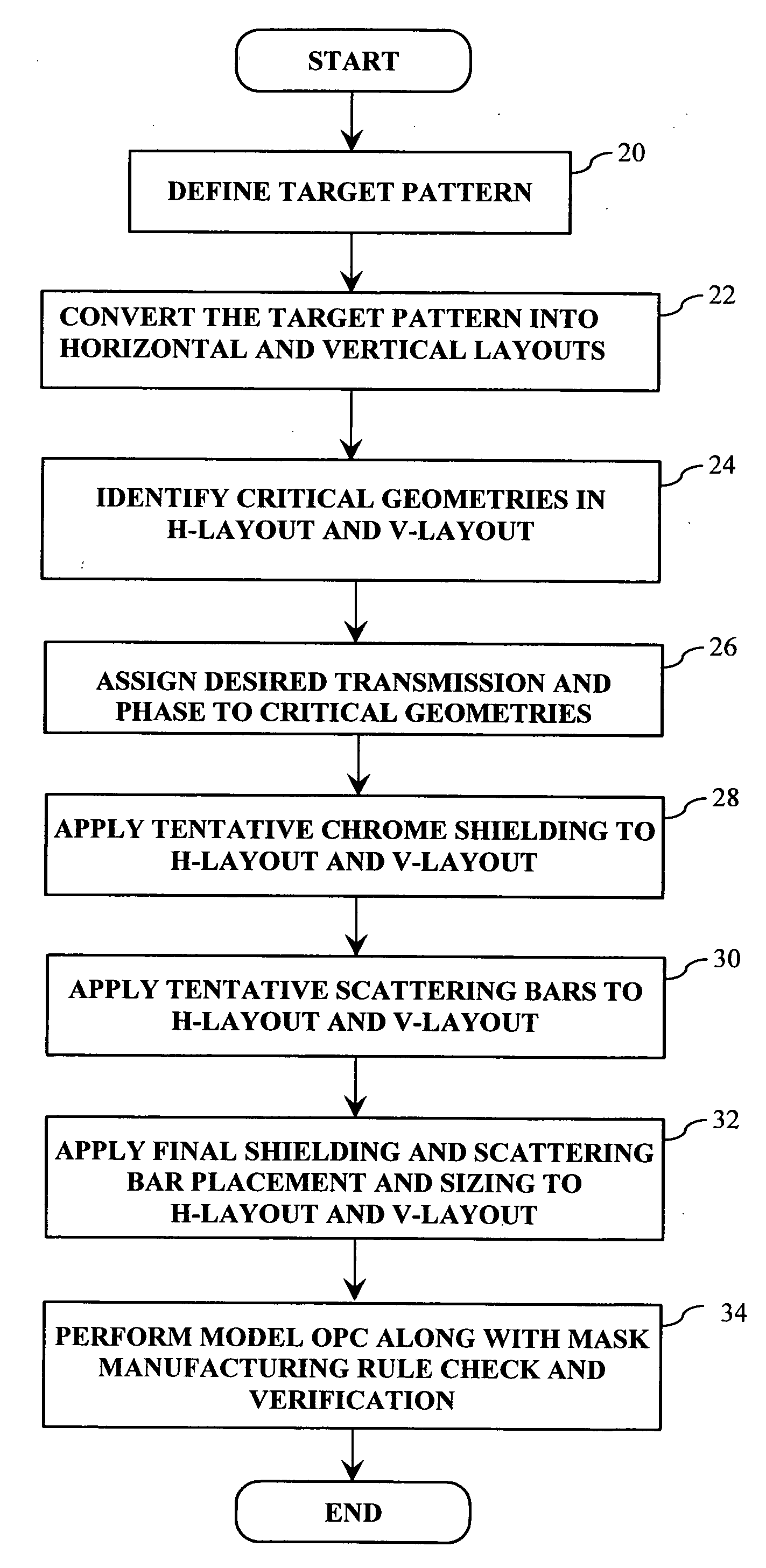
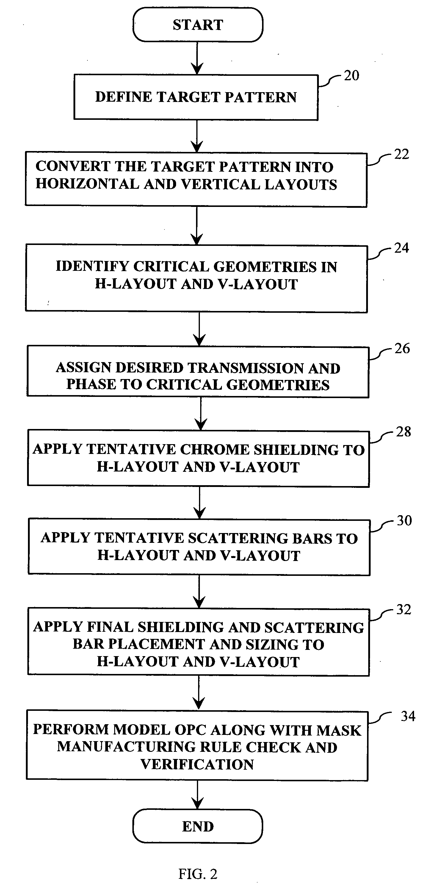
[0030] As explained in more detail below, the double exposure technique of the present invention decomposes the target pattern into multiple tri-tone masks, which when illuminated provide for improved scatter bar trimming and improved imaging performance.

[0031] More specifically, FIG. 2 is an flow-chart illustrating a first embodiment of the present invention. Referring to FIG. 2, the first step (Step 20) in the process is to identify and read in the target pattern which is to be imaged on the substrate (or wafer, etc.). The target pattern can be represented in, for example, GDSII design data or any other suitable data format. The next step (Step 22) is to convert the target pattern into horizontal (H) and vertical (V) layouts, and identify critical geometries (Step 24) in both the horizontal and vertical layouts. It is noted that when separating the target design into H and V layouts, initially the layouts are identical and correspond to the target pattern. However, as explained i...


PUM


Abstract

A method of generating complementary masks based on a target pattern having features to be imaged on a substrate for use in a multiple-exposure lithographic imaging process. The method includes the steps of: defining an initial H-mask corresponding to the target pattern; defining an initial V-mask corresponding to the target pattern; identifying horizontal critical features in the H-mask having a width which is less than a predetermined critical width; identifying vertical critical features in the V-mask having a width which is less than a predetermined critical width; assigning a first phase shift and a first percentage transmission to the horizontal critical features, which are to be formed in the H-mask; and assigning a second phase shift and a second percentage transmission to the vertical critical features, which are to be formed in the V-mask. The method further includes the step of assigning chrome to all non-critical features in the H-mask and the V-mask. The non-critical features are those features having a width which is greater than or equal to the predetermined critical width. The non-critical features are formed in the H-mask and the V-mask utilizing chrome. The target pattern is then imaged on the substrate by imaging both the H-mask and V-mask.

Description

CLAIM OF PRIORITY [0001] This patent application, and any patent(s) issuing therefrom, claims priority to U.S. provisional patent application No. 60 / 670,285, filed on Apr. 12, 2005, entitled “Double exposure Lithography (DEL) techniques with mutual scattering bar trimming and polarization”, which is incorporated herein by reference in its entirety.TECHNICAL FIELD [0002] The technical field of the present invention relates generally to a method, program product and apparatus for performing a double exposure lithography, which utilizes a tri-tone mask and which provides for improved scatter bar trimming BACKGROUND OF THE INVENTION [0003] Lithographic apparatus can be used, for example, in the manufacture of integrated circuits (ICs). In such a case, the mask may contain a circuit pattern corresponding to an individual layer of the IC, and this pattern can be imaged onto a target portion (e.g., comprising one or more dies) on a substrate (silicon wafer) that has been coated with a laye...

Claims


Application Information

Patent Timeline
IPC IPC(8): G06F17/50G03F1/00G21K5/00G06F19/00A61N5/00G21G5/00
CPCG03F7/70466G03F1/144G03F1/70G03F1/36G03F7/705G06F30/398G06F2111/06G06F2119/18
Inventor CHEN, JANG FUNGHSU, DUAN-FU STEPHENVAN DEN BROEKE, DOUGLAS
Owner ASML NETHERLANDS BV
Why Eureka
Try Eureka