Anti-reverse input clutch

a technology of input clutch and input member, which is applied in the direction of interlocking clutches, couplings, braking systems, etc., can solve the problems of increasing the manufacturing cost of the entire clutch, affecting the design freedom of the clutch, so as to reduce the time and cost of manufacturing, and facilitate the formation

Inactive Publication Date: 2006-12-14
NTN CORP
View PDF14 Cites 22 Cited by
  • Summary
  • Abstract
  • Description
  • Claims
  • Application Information

AI Technical Summary

Benefits of technology

[0012] Since the output member comprises the output shaft and the cam member which are separate members from each other, each of the output shaft and the cam shaft can be easily formed, so that it is possible to significantly reduce the time and cost for manufacturing the output member and improve the freedom of design thereof and thus to reduce the manufacturing cost of the entire clutch. Such clutches can therefore be stably mass-produced.

Problems solved by technology

Thus, the output member 52 is complicated in structure and only limited options are available as methods for forming such an output member 52.
It is therefore troublesome and thus costly to form such an output member, which will push up the manufacturing cost of the entire clutch.

Method used


Image

  • Anti-reverse input clutch
  • Anti-reverse input clutch
  • Anti-reverse input clutch

Examples


Embodiment Construction

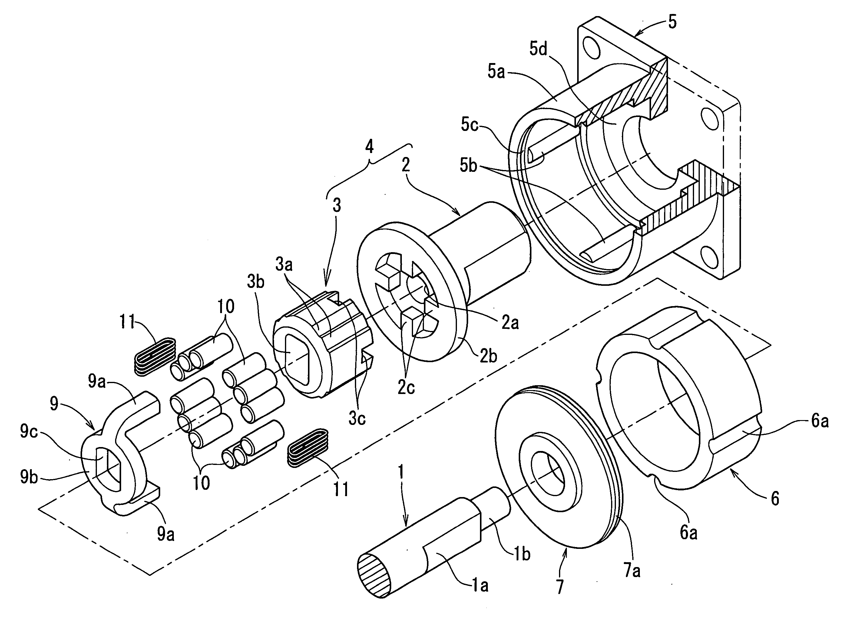
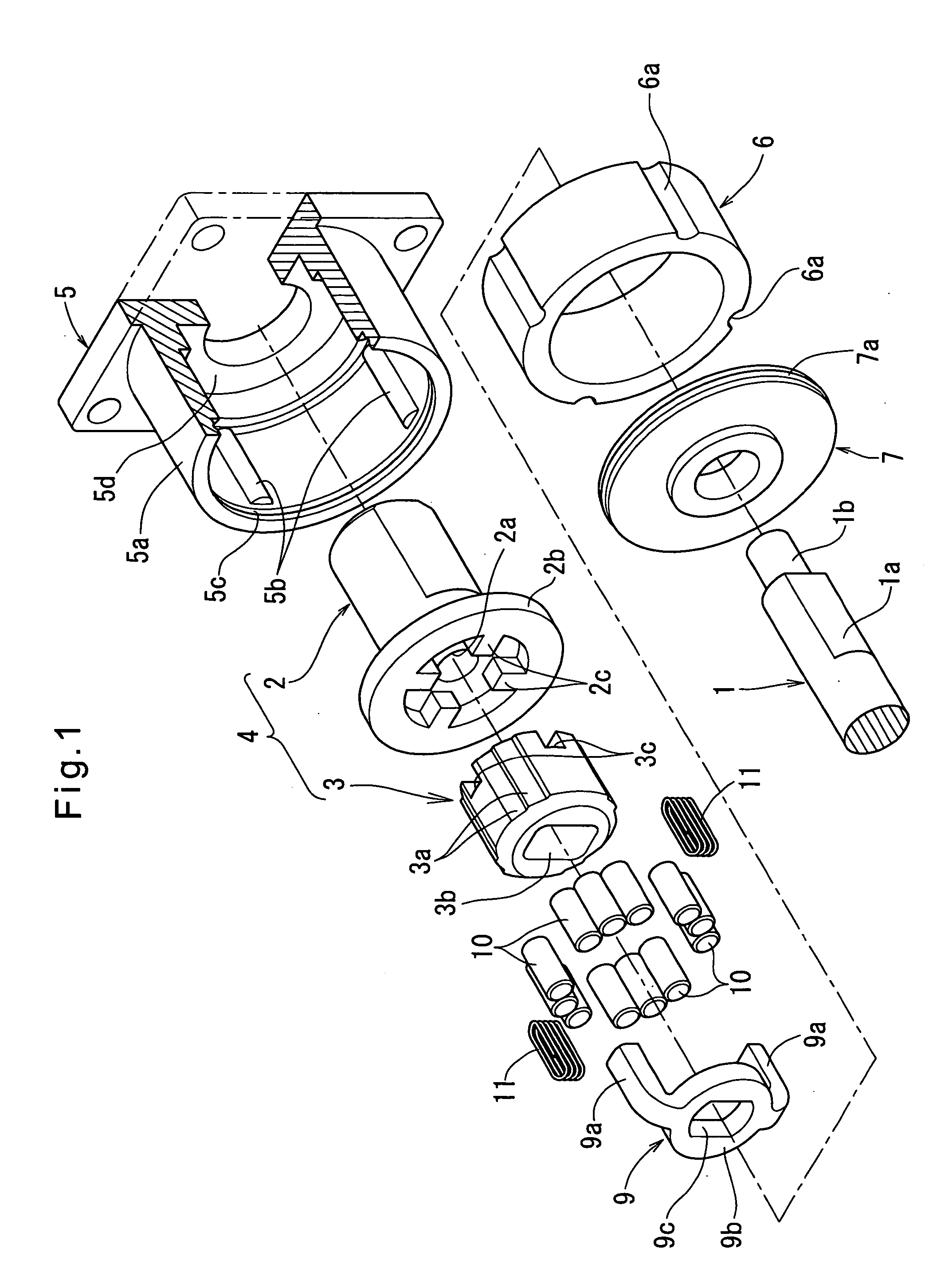
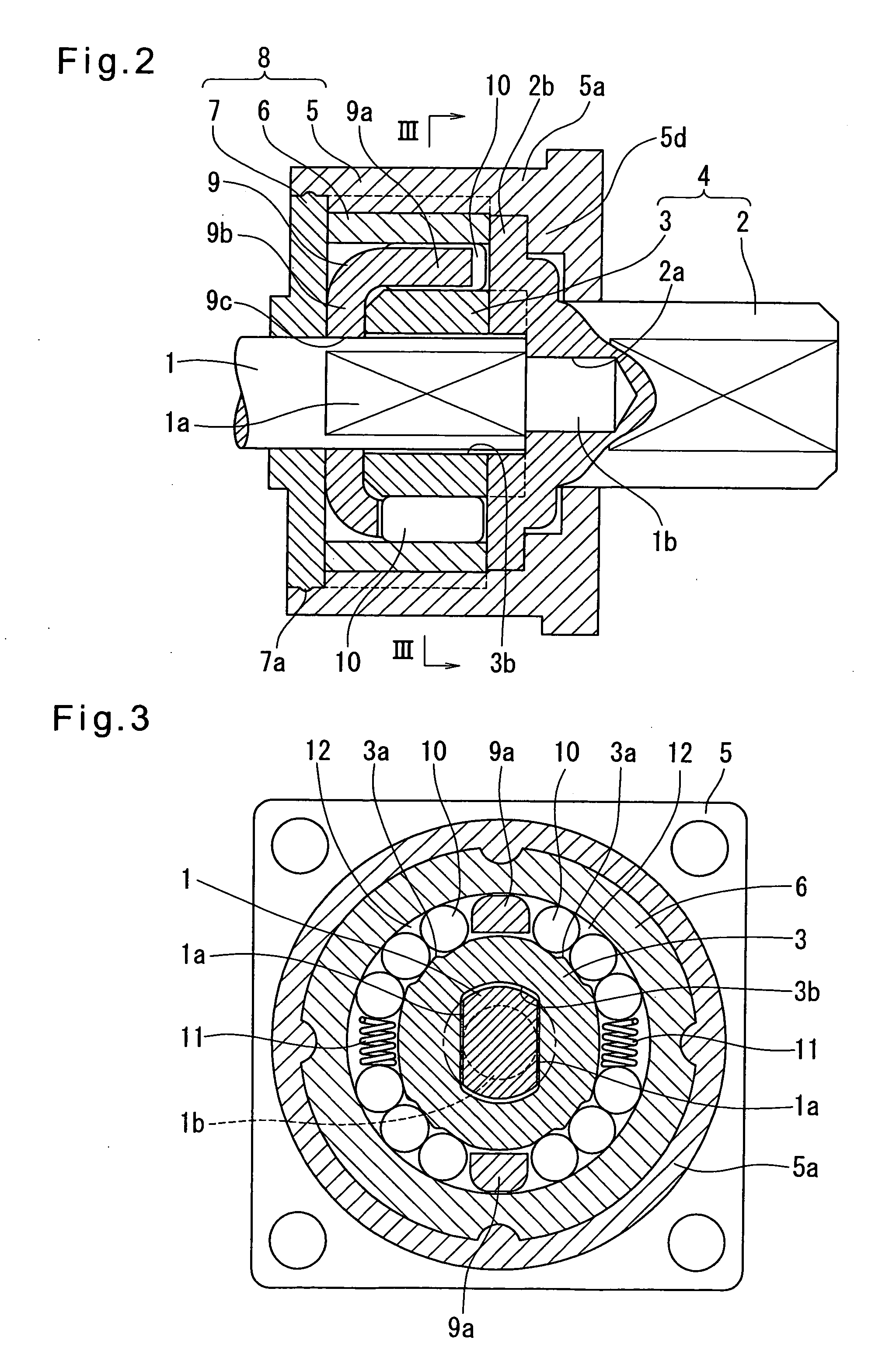
[0023] Now referring to FIGS. 1 to 7, the embodiments according to the present invention are described. First, FIGS. 1 to 3 show the first embodiment. As shown in FIGS. 1 and 2, the anti-reverse input clutch of this embodiment includes an input shaft (input member) 1, an output member 4 comprising an output shaft 2 and an inner ring (cam member) 3 defining a plurality of cam surfaces 3a on the outer periphery thereof, a stationary member 8 comprising a housing 5, an outer ring 6 and a presser lid 7, and a retainer 9 having two legs 9a inserted between the inner ring 3 and the outer ring 6. Cylindrical rollers (rolling elements) 10 and springs (elastic members) 11 are disposed between the two legs 9a of the retainer. The output shaft 2 and the inner ring 3, which constitute the output member 4, are preferably made of sintered metal, forged metal or plastic.

[0024] The input shaft 1 has a front end portion formed with two parallel flat surfaces 1a on its outer periphery and extending ...


PUM


Abstract

An anti-reverse input clutch is provided which includes an output member including an output shaft held so as to be rotatable about the axis of an input member, and a cam member which is a separate member from the output shaft and on which cam surfaces are formed. The cam member is rotationally fixed to the output shaft. Thus, each of the output shaft and the cam shaft can be easily formed, so that it is possible to significantly reduce the time and cost for manufacturing the output member and improve the freedom of design thereof.

Description

BACKGROUND OF THE INVENTION [0001] This invention relates to an anti-reverse input clutch which transmits torque only from an input member to an output member and not from the output member to the input member. [0002] Such an anti-reverse input clutch transmits torque applied to the input member in either direction to the output member but does not transmit reverse input torque applied to the output member to the input member. FIGS. 8A and 8B show a clutch having such a reverse input blocking function disclosed in Japanese patent publication 2-271116A. This clutch includes an input member 51 and an output member 52. A pin 53 secured to the input member 51 is inserted in a pin hole 54 formed in the output member with a slight clearance defined therebetween in the rotational direction. The clutch further includes a stationary outer ring 55 having a cylindrical inner surface radially opposed to the outer periphery of the output member 52, defining wedge-shaped spaces 56 therebetween wh...

Claims


Application Information

Patent Timeline
Patent Type & Authority Applications(United States)
IPC IPC(8): F16D41/06
CPCF16D41/105
Inventor ITOMI, SHOJI
Owner NTN CORP
Why Eureka
Try Eureka