Bond capillary design for ribbon wire bonding

a ribbon wire and capillary design technology, applied in the field of devices and methods for bonding ribbon wires, can solve the problems of affecting the bonding effect,

Active Publication Date: 2006-12-14
TEXAS INSTR INC
View PDF22 Cites 94 Cited by
  • Summary
  • Abstract
  • Description
  • Claims
  • Application Information

AI Technical Summary

Benefits of technology

[0007] The present invention overcomes the limitations of the prior art by providing an improved device and method for bonding wires to various substrates. Accordingly, the following presents a simplified summary of the invention in order to provide a basic understanding of some aspects of the invention. This summa

Problems solved by technology

One problem associated with wire bonding is the handling of the wire throughout the bonding process, and the breaking or severing of the wire after the bond has been made.
Typically, with small diameter wires (circular cross-section wires having diameters of less than 0.025 inches), such a pulling action is sufficient, and does not cause significant damage to the substrate.
Accordingly, when the conventional bonding tools are used with the thicker ribbon wires, the pulling force required to break the ribbon wire tends to deleteriously defor

Method used


Image

  • Bond capillary design for ribbon wire bonding
  • Bond capillary design for ribbon wire bonding
  • Bond capillary design for ribbon wire bonding

Examples


Embodiment Construction

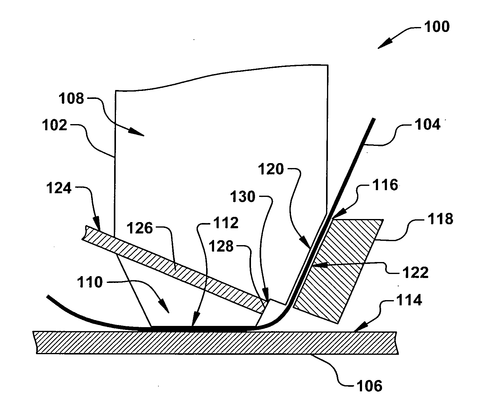
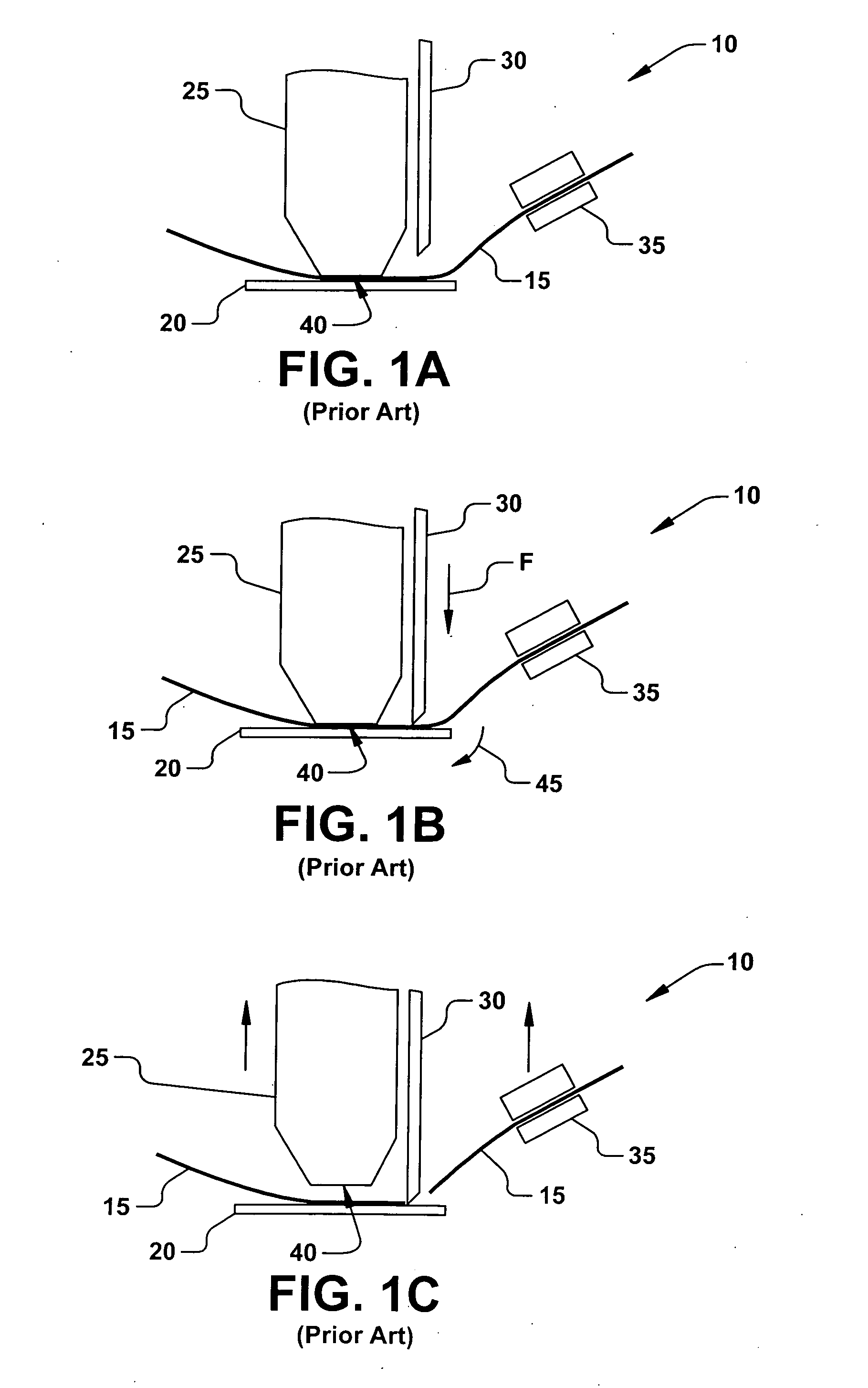
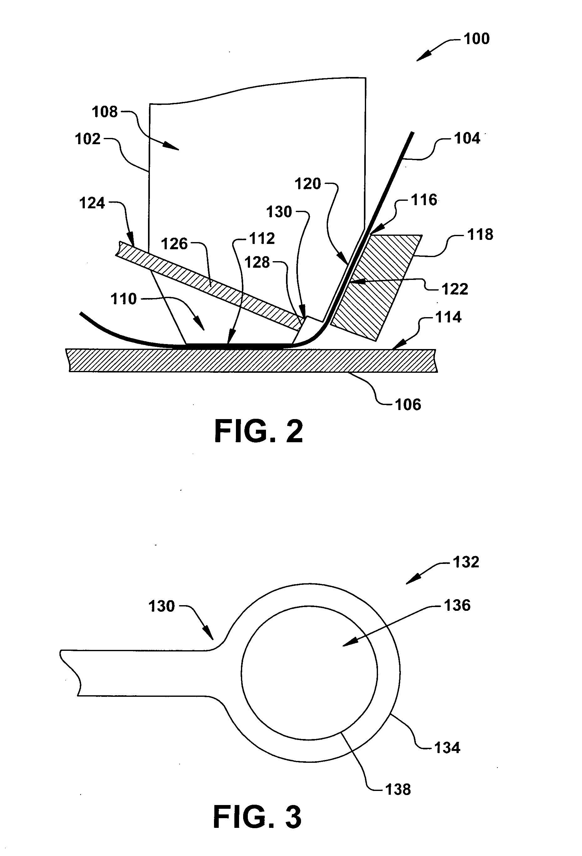
[0018] The present invention is directed towards an apparatus and method for bonding a wire to substrate or workpiece, such as an integrated circuit (IC) and / or leadframe assembly. More particularly, the present invention provides a robust and reliable device and process for bonding a rectangular cross-section ribbon wire to the substrate, wherein damages or deformations to the substrate seen in conventional bonding apparatuses and processes are substantially mitigated. Accordingly, the present invention will now be described with reference to the drawings, wherein like reference numerals are used to refer to like elements throughout. It should be understood that the description of these aspects are merely illustrative and that they should not be taken in a limiting sense. In the following description, for purposes of explanation, numerous specific details are set forth in order to provide a thorough understanding of the present invention. It will be evident to one skilled in the ar...


PUM

PropertyMeasurementUnit
Diameteraaaaaaaaaa

Abstract

A device (100) and method (200) for bonding a ribbon wire (104) to a workpiece (106) comprising feeding the ribbon wire through a passageway (116) of an ultrasonic bond capillary (102) and clamping the ribbon wire against an engagement surface (120) of the bond capillary via a clamping jaw (118) operably coupled to the bond capillary. The ribbon wire (104) is bonded to the workpiece (106) along a bonding surface (112) of the bond capillary (102) and penetrated, at least partially, between the bonding surface and the engagement surface (120) of the bond capillary by a cutting tool (124). The cutting tool (124) may comprise an elongate member (126) positioned between the bonding surface (112) and engagement surface (120), and may have a cutting blade (128) positioned at a distal end (130) thereof. The cutting tool (124) may further comprise a ring cutter (132), wherein the ribbon wire passes through a ring (134) having a cutting surface (138) defined about an inner diameter thereof.

Description

FIELD OF THE INVENTION [0001] The present invention relates generally to semiconductor devices and processes, and more particularly to device and method for bonding a ribbon wire to a workpiece. BACKGROUND OF THE INVENTION [0002] In the semiconductor industry, wire bonding is commonly performed to electrically interconnect an integrated circuit (IC), such as a semiconductor die or chip, to various structures, such as a metal leadframe. Wedge bonding, for example, is a conventional method used to bond thin wires, such as thin aluminum or gold wire, between a bonding point on the semiconductor die to another point, such as a lead finger of the leadframe. Conventionally, in order to initiate a bond, the wire is pressed against the IC and / or leadframe with a tip of a bonding tool. The bonding tool is ultrasonically vibrated for a period of tens of milliseconds, wherein a plane of motion of the tip of the bonding tool is generally parallel to the surface of the semiconductor chip to whic...

Claims


Application Information

Patent Timeline
IPC IPC(8): B23K31/02B23K37/00
CPCB23K20/004H01L2224/78318B23K20/106H01L24/45H01L24/78H01L24/85H01L2224/45014H01L2224/45015H01L2224/45124H01L2224/45144H01L2224/4847H01L2224/78313H01L2224/85205H01L2924/01013H01L2924/01029H01L2924/01079H01L2924/01082H01L2924/14H01L2924/2076B23K20/005H01L2924/014H01L2924/01033H01L2924/01006H01L2924/00014H01L2924/00H01L24/48H01L2924/00015H01L2924/206B23K1/06B23K37/00
Inventor LANGE, BERNHARD P.KUMMERI, STEVEN ALFRED
Owner TEXAS INSTR INC
Why Eureka
Try Eureka