
Small vehicle jack apparatus

Inactive Publication Date: 2006-12-14
MOJACK DISTRIBUTORS
View PDF14 Cites 30 Cited by
  • Summary
  • Abstract
  • Description
  • Claims
  • Application Information

AI Technical Summary

Benefits of technology

[0010] A complete apparatus is necessary, where the wheels of the vehicle may be used to elevate the entire end of a vehicle, rather than relying on the frame or other similar contact points available with typical hydraulic jacks for such a vehicle. A means to provide use of a jack with a stationary vehicle is desired, where the supporting structure can be moved into position on a vehicle, without requiring movement of the vehicle onto the jack means itself.
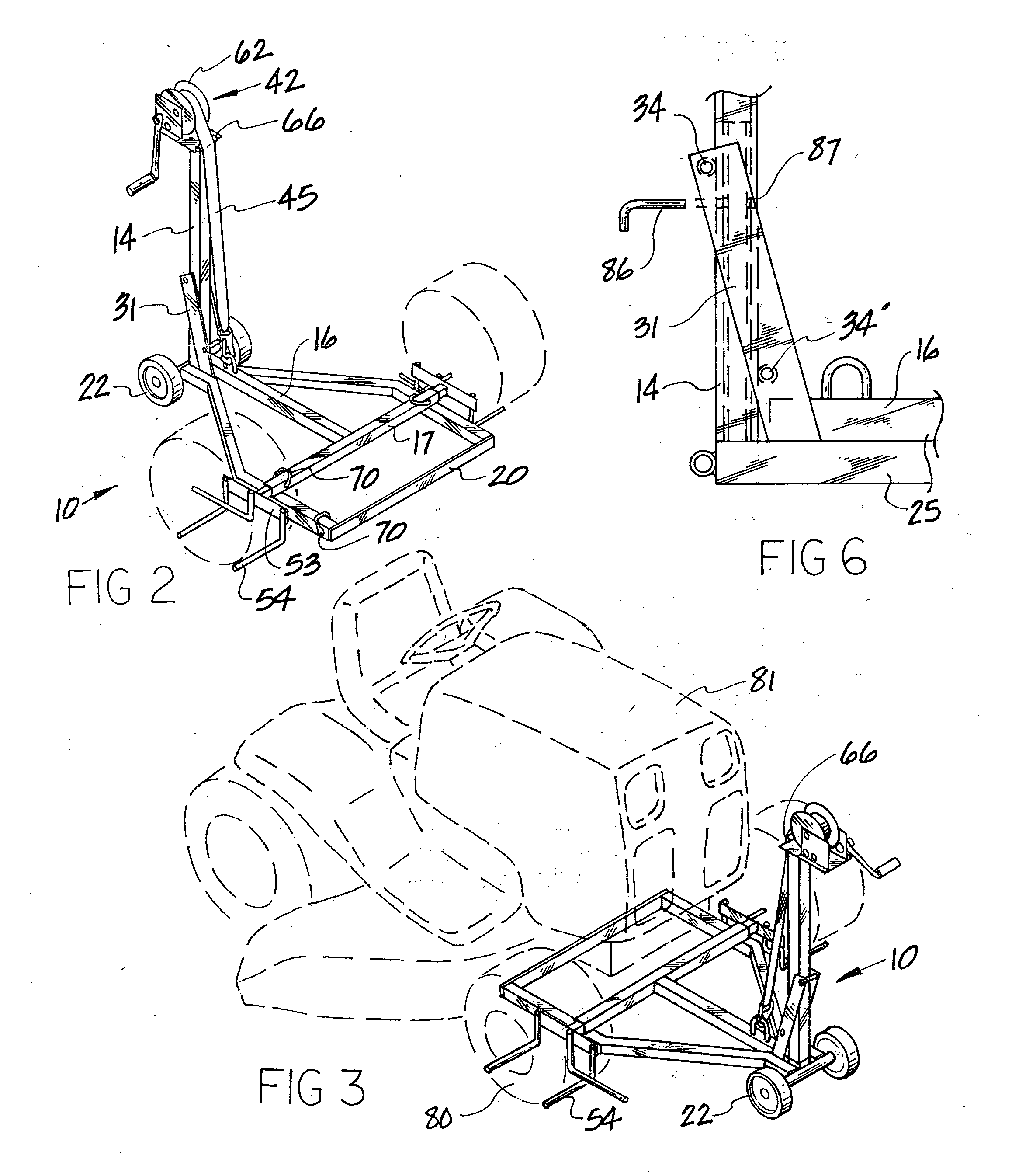
[0016] Once the lifting frame is positioned so that the vertical frame bar is situated between the angled guide members, a top roller is placed through its receiving apertures located on the terminating ends of the guide members, so that the vertical frame bar is restrained within the guide member gap area. A bottom roller is also positioned on the opposite side of the vertical frame bar, through the side guide members. The bottom roller, the parallel guide members and top roller function as a sleeve, which fits around the vertical frame bar, allowing the lifting frame to be moved upward and downward, with the gap between the guide members allowing some limited horizontal motion of the lifting frame. This allows for easy adjustment to the position of the lifting frame.
[0018] The extension bar is provided, when greater height is desired, than can be obtained from a standard vertical frame bar. Also, the separate extension bar is provided for the simple need of disassembly and storage when so desired. Since both situations are generally desired, a extension bar is typically used with this apparatus.
[0019] The extension bar defines an inner cavity which allows the length of the vertical frame bar to be inserted completely into the extension bar. The extension bar preferably has a width similar to the center bar, with the gap defined between the guide members sufficient to allow said guide members to move freely over the extension bar.
[0023] One advantage of having a separate extension bar is that the overall height capabilities of the jack can be varied, according to the length of the extension bar. Use of the strap denies the need for any type of hydraulic system, with the winch apparatus providing sufficient force to the strap, especially if the winch apparatus has a geared ratio with regard to the handle movement.

Problems solved by technology

The use of hydraulic floor jacks do not always provide a single stable support structure, and jack stands are often the wrong size with regard to the elevation requirements for the small vehicles.
In some situations, the angle of the vehicle necessary to accomplish the desired elevation of one end of the vehicle, makes the use of small jacks unwieldy, since small hydraulic system jacks only have a single contact point.
As the contact point rotates by virtue of the elevation difference between the front and back end of the vehicle, the contact point with the hydraulic jack may become unstable.
Further, the amount of elevation necessary will often exceed a hydraulic jack assembly's capability.

Method used


Image

  • Small vehicle jack apparatus
  • Small vehicle jack apparatus
  • Small vehicle jack apparatus

Examples


Embodiment Construction

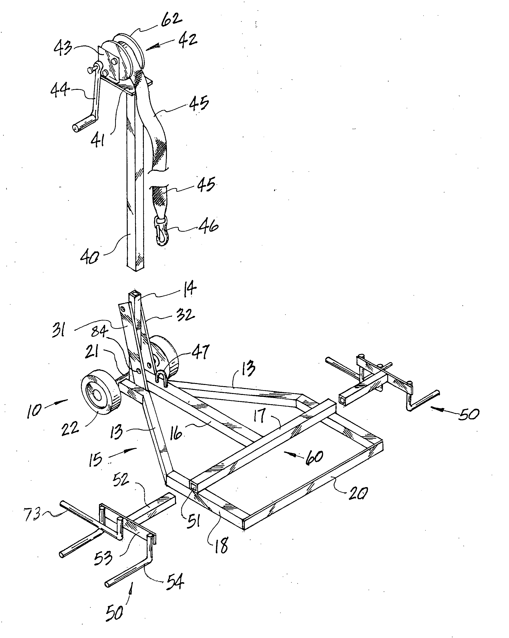
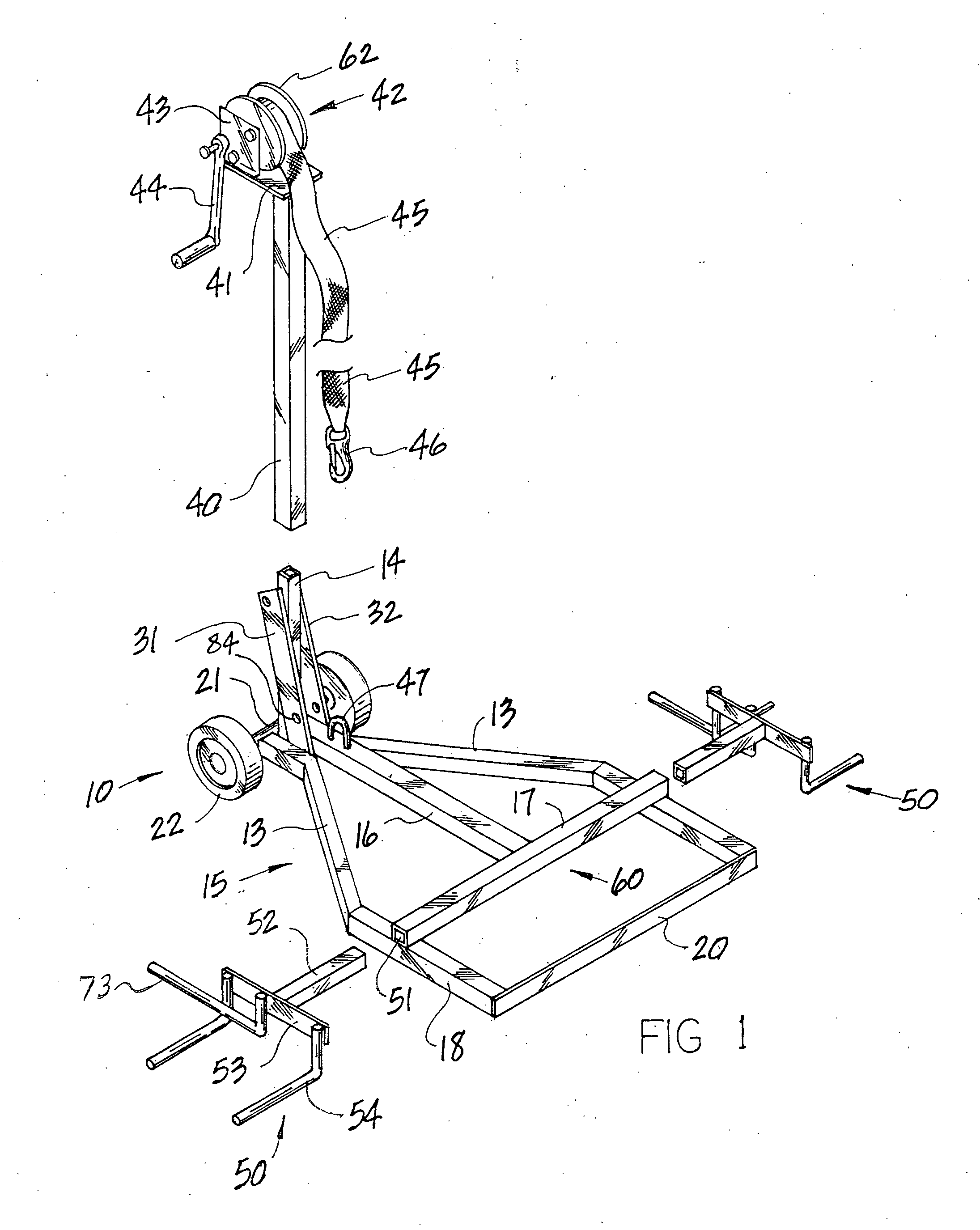
[0031] Referring to FIG. 1, the improved small vehicle jack apparatus 10 is shown. Said apparatus 10 is comprised of a support frame 15, a lifting frame 60, a lifting means 42, and a wheel support means 50. The support frame 15 is comprised of two generally parallel crossbar rest members 18 and 19, which are spaced apart by a front member 20. These members 18, 19 and 20, comprise the portion of the support frame 15 that is actually intended to be moved underneath the vehicle.

[0032] The crossbar rest members 18 and 19 are attached to the front member 20 ends, with angled members 13 fixed to the crossbar rest member 18 and 19 rear ends. The angled side members 13 are angled in relation to each other so that the distance between them becomes closer toward each other along their length from the front toward the rear. The rear ends of the angled side members 13 define end portions 25 that are fixed in relation to each other and which allow a vertical frame bar 14 to be fixed in a vertic...


PUM


Abstract

A small vehicle jack, having the ability to lift vehicles having a variety of wheel bases, and axle configurations. A support frame provides stability for a vertical bar, which supports a winch means. The winch means raises a lifting frame using a strap means, and the lifting frame which follows the vertical bar using an improved sleeve means, in which rollers are used on either side of the vertical bar. The jack may have adjustable and detachable wheel support means, in which the wheels of the vehicle are used as the contact points to raise the vehicle. The jack may also be used without wheel support means, but instead use hook means to attach to an axle.

Description

BACKGROUND OF THE INVENTION [0001] Referring now to U.S. Pat. No. 4,066,243 (Johnson), a jack for the use with automobile bumpers is shown, in which a frame is provided as a support means for a vertical pipe, which has a sleeve, which moves upward and downward around said pipe. A typical floor jack provided the upward lifting force against the sleeve, where the floor jack was attached to the sleeve portion through a ring. This device required a secondary jack, and was limited to the lifting of a vehicle body parts which would comprise a bumper. [0002] Referring now to U.S. Pat. No. 4,123,038 (Meyers), an apparatus is disclosed in which an elaborate load bearing frame is provided, where the apparatus operates using two separate hydraulic jacks. There is no realistic application of this type of device with a small tractor or riding lawn mower. [0003] Portable jacks for small tractors are specifically exampled in U.S. Pat. No. 4,549,721 (Stone), in which a screw-scissors jack was opera...

Claims


Application Information

Patent Timeline
IPC IPC(8): B66F7/02
CPCB66F7/02
Inventor KRUG, NORMAN J.
Owner MOJACK DISTRIBUTORS
Learn More