Optical sheet, backlight unit, electro-optical device, electronic apparatus and method for manufacturing the optical sheet

a technology of electrooptical devices and optical sheets, applied in the field of optical sheets, can solve the problems of difficult light collection and luminance, difficult bonding between first lens material and second lens material, etc., and achieve the effects of reducing luminance irregularities, high luminance, and high luminan

Inactive Publication Date: 2006-12-14
SEIKO EPSON CORP
View PDF11 Cites 17 Cited by
  • Summary
  • Abstract
  • Description
  • Claims
  • Application Information

AI Technical Summary

Benefits of technology

[0008] An advantage of the present invention is to solve the above problems and provide an optical sheet, a backlight unit, an electro-optical device, an electronic apparatus, and a method for manufacturing the optical sheet which has high luminance and is able to reduce luminance irregularity.
[0009] A method for manufacturing an optical sheet of the present invention according to one aspect of the invention includes: (a) discharging a first lens material in liquid form that is to become a material for micro lenses on a sheet in a dot array; (b) semi-curing the first lens material arranged on the sheet; (c) discharging a second lens material in liquid form that is to become the material for the micro lenses towards gap portions between dots of the first lens material; and (d) forming a micro lens array by full curing the first and the second lens materials.
[0010] In the above-mentioned method, it is preferable that the first lens material be discharged so that the first lens material is deposited on the sheet in the dot array [first discharging process (a)]. The deposited first lens material cures into the semi-cured state [semi-curing process (b)]. Next, the second lens material is discharged towards the gap portions between the dots of the first lens material [second discharging process (c)]. And the first and the second lens materials are fully cured so as to form the micro lens array [fully curing process (d)]. Therefore, as the second lens material is discharged while the first lens material is in semi-cured state, the first lens material and the second lens material do not bond easily. And because the second lens material spreads into the gap portions between the dots of the first lens in a state that the first lens material is maintaining its shape, the top of the sheet is covered with the micro lenses, which enables to obtain high luminance and reduce luminance irregularity.
[0011] A method for manufacturing the optical sheet according to another aspect of the invention includes applying a liquid-repellent treatment on the sheet before the first discharging process [liquid-repellent treatment process].
[0012] In the above-mentioned method, it is preferable that the discharged liquid droplets of the first lens material being deposited on the sheet are to have a large contact angle by the liquid-repellent treatment so that they are formed into the liquid droplets with large curvature. This facilitates an accumulation of the second lens material into the gap portions between the dots of the first lens material, which enables the micro lenses to cover the sheet easily without gaps.
[0013] A method for manufacturing the optical sheet according to another aspect of the invention includes forming the dot array by discharging the first lens material in a staggered arrangement in the first discharging process (a), and discharging the second lens material into the gap portions between the dots of the first lens material in the second discharging process (c).

Problems solved by technology

Therefore, it was difficult to collect light and provide enough luminance.
Therefore, as the second lens material is discharged while the first lens material is in semi-cured state, the first lens material and the second lens material do not bond easily.

Method used


Image

  • Optical sheet, backlight unit, electro-optical device, electronic apparatus and method for manufacturing the optical sheet
  • Optical sheet, backlight unit, electro-optical device, electronic apparatus and method for manufacturing the optical sheet
  • Optical sheet, backlight unit, electro-optical device, electronic apparatus and method for manufacturing the optical sheet

Examples


modification example 1

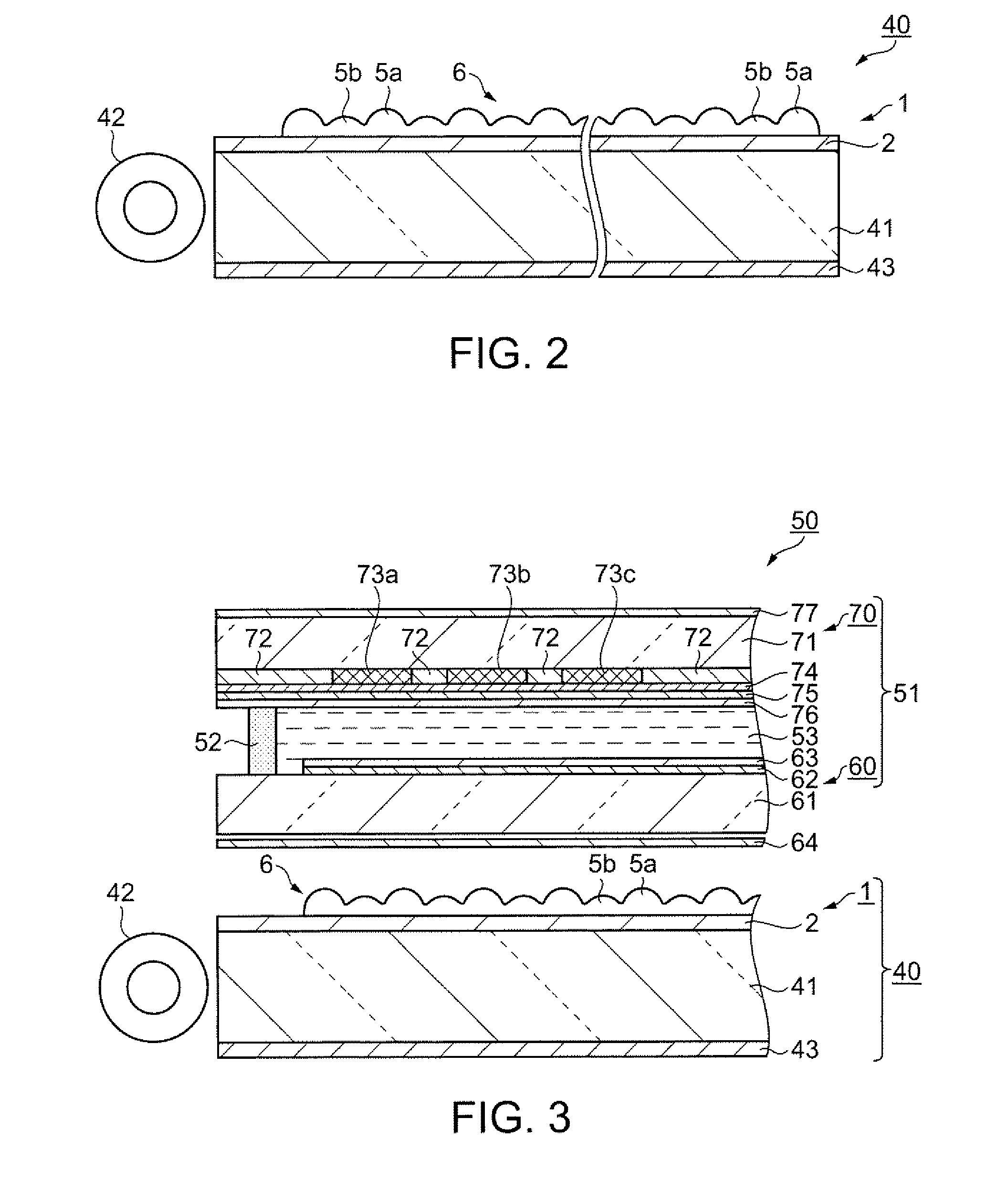
[0085] According to the present embodiment, the curvatures of the first and the second micro lenses 5a and 5b are formed approximately the same, but it is not limited to this. For example, as shown in FIG. 7, the first and the second micro lenses 5a and 5b with different curvatures may be formed. By doing so, for example, when the curvature of the second micro lens 5b is formed smaller than the first micro lens 5a, a focusing length towards the liquid crystal display unit 51 will be approximately equal even if the height of the lenses are different.

modification example 2

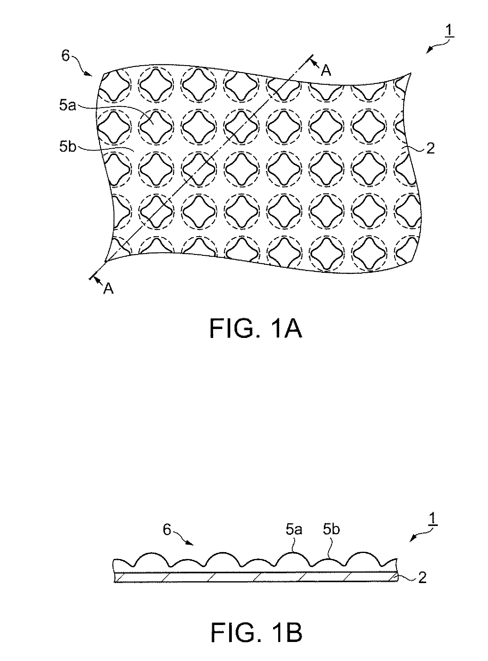
[0086] According to the present embodiment, the size of the first and the second micro lenses 5a and 5b are formed approximately the same, but it is not limited to this. For example, as shown in FIG. 8, the first and the second micro lenses 5a and 5b with different sizes may be formed. Even doing so, as the sheet 2 is covered with the micro lens array 6, diffusion can be improved.

modification example 3

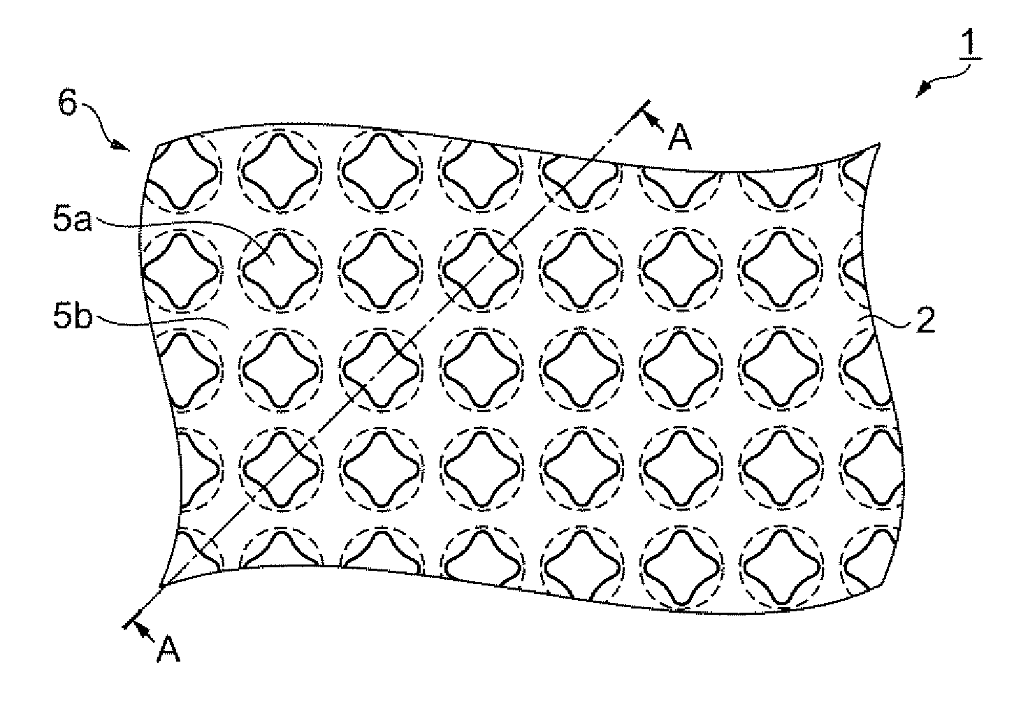
[0087] According to the present embodiment, the first micro lens 5a is disposed in a square lattice, but it is not limited to this. For example, as shown in FIG. 9, it may be formed in a staggered arrangement. By doing so, the space between the dots of the first micro lens 5a become dense, which enables to cover the sheet 2 with the first and the second micro lenses 5a and 5b easily without gap, by relatively small amount of discharge of the second lens material.


PUM


Abstract

A method for manufacturing an optical sheet, comprises: (a) discharging a first lens material in liquid form being a material for a micro lens on a sheet in a dot array; (b) semi-curing the first lens material arranged on the sheet; (c) discharging a second lens material in liquid form being a material for the micro lens towards gap portions between the dots of the first lens material; and (d) forming a micro lens array by full curing the first and the second lens materials.

Description

BACKGROUND OF THE INVENTION [0001] 1. Technical Field [0002] The present invention relates to an optical sheet, a backlight unit, an electro-optical device, an electronic apparatus, and a method for manufacturing the optical sheet. [0003] A backlight unit is used as a light source for a liquid crystal display device such as a notebook personal computer, a portable terminal and the like, and functionally, high luminance and uniform luminance are demanded. [0004] 2. Related Art [0005] A conventional backlight unit is configured with a light source, a light guide plate which guides light from the light source to an entire surface of a plane, an optical sheet (diffuser) which diffuses light irradiated from the light guide plate, and the like. A known optical sheet is the one which a plurality of micro lenses are formed on the sheet. [0006] JP-A-6-27454 is an example of related art. [0007] However, as the above optical sheet has gap portions between the micro lenses, light rays which pas...

Claims


Application Information

Patent Timeline
Patent Type & Authority Applications(United States)
IPC IPC(8): B65H39/00
CPCG02B3/0056G02B3/0031G02F1/1335
Inventor HASEI, HIRONORIINAGAKI, AKIRA
Owner SEIKO EPSON CORP
Why Eureka
Try Eureka