Calibration apparatus and method for array antenna

a technology of array antennas and apparatuses, which is applied in the direction of antennas, diversity/multi-antenna systems, transmission monitoring, etc., can solve the problems of limiting the number of simultaneously communicable channels, i.e., channel capacity, and enlargement of apparatus scale and circuit scal

Inactive Publication Date: 2006-12-14
FUJITSU LTD
View PDF7 Cites 55 Cited by
  • Summary
  • Abstract
  • Description
  • Claims
  • Application Information

AI Technical Summary

Benefits of technology

[0028] (5) Moreover, when a spread spectrum signal (in particular, spread spectrum signal spread with a different spread code according to antenna element) is produced as a calibration signal, the diffusion code enables the calibration si

Problems solved by technology

That is, the CDMA system is based on an access mode in which channels are allocated through the use of codes to carry out simultaneous communications, while interference with signals from other channels under the simultaneous communication condition occurs, which consequently limits the number of simultaneously communicable channels, i.e., the channel capacity.
For thi

Method used


Image

  • Calibration apparatus and method for array antenna
  • Calibration apparatus and method for array antenna
  • Calibration apparatus and method for array antenna

Examples


first embodiment

[B] Description of First Embodiment

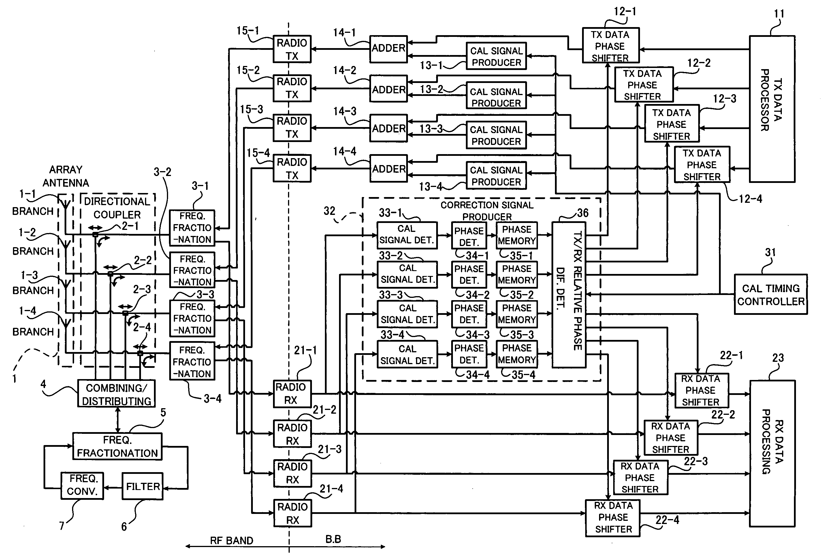
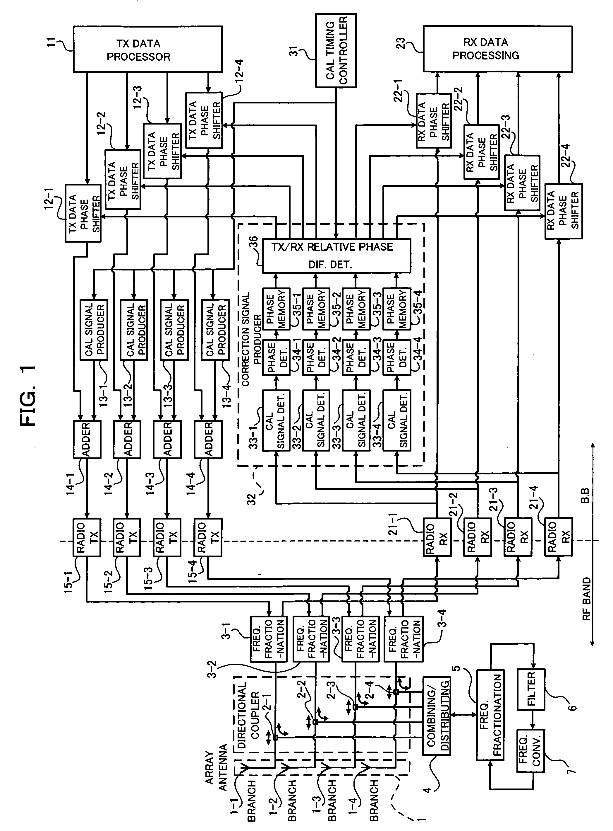
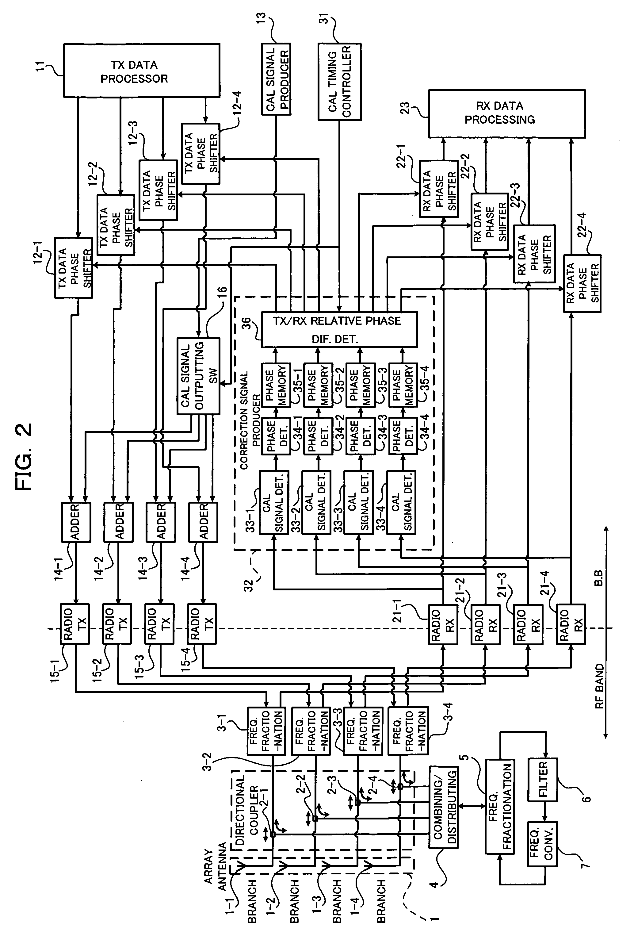
[0061]FIG. 2 is a block diagram showing a configuration of an array antenna communication system according to a first embodiment of the present invention. The system shown in FIG. 2 differs from the system described above with reference to in FIG. 1 in that, in place of the aforesaid calibration signal producers 13-i, a single calibration signal producer (common calibration signal producing unit) 13 is provided in common (commonized) with respect to the respective branch antennas 1-i and a calibration signal outputted from this calibration signal producer 13 is selectively (in a time division fashion) inputted through a calibration signal outputting switch [calibration signal selective-outputting unit (hereinafter equally referred to simply as a “switch”)]16 to the adders 14-i. Moreover, the control of the selective (time division) output (switch 16) of the calibration signal is executed in the calibration timing controller 31. In FIG. 2, unless ot...

second embodiment

[C] Description of Second Embodiment

[0067]FIG. 3 is a block diagram showing a configuration of an array antenna communication system according to a second embodiment of the present invention. The system shown in FIG. 3 relates to a configuration for time-division-multiplexing transmission / reception system main signals, and differs from the system configuration described above with reference to FIG. 1 in that a time-division demultiplexer 17 is provided in the transmission system so that, in place of the transmission data phase shifter 12-i, the calibration signal producer 13-i and the adder 14-1 for each branch antenna 1-i (for each radio transmitter 15-i), each of a transmission(TX) data phase shifter 12, a calibration signal producer 13 and an adder 14 is provided in common (commonized) with respect to the branch antennas 1-i while a time-division multiplexer 24 is provided in the reception system so that, in place of the reception (RX) data phase shifter 22-i for each branch ante...

third embodiment

[D] Description of Third Embodiment

[0081]FIG. 6 is a block diagram showing a configuration of an array antenna communication system according to a third embodiment of the present invention. The system shown in FIG. 6 is based upon the time-division multiplexing configuration described above with reference to FIG. 3 and is designed such that the array antenna has a transmission and reception diversity arrangement, and its transmission and reception shared section includes an main array antenna 1A having a plurality of (for example, N=4) sensor elements (branch antennas) 1A-1 to 1A-N, directional couplers 2A-1 to 2A-N each provided for each of the branch antennas 1A-i (i=1 to N), frequency fractionation units 3A-1 to 3A-N provided for each of the branch antennas 1A-i, a diversity antenna 1D having a plurality of (for example, N=4) sensor elements (branch antennas) 1B-1 to 1B-N, directional couplers 2B-1 to 2B-N each provided for each of the branch antennas 1B-i (i=1 to N), frequency f...


PUM


Abstract

The present invention relates to a calibration apparatus for an array antenna having a plurality of antenna elements. The calibration apparatus comprises a conversion unit detecting a calibration signal from an output of a transmission unit to convert the detected calibration signal into a predetermined reception radio frequency and outputting the converted calibration signal together with a reception main signal to a reception unit, a detecting unit detecting the calibration signal from an output of the reception unit for each of the antenna elements to obtain a relative phase difference between the calibration signals, and a phase correcting unit correcting a phase difference with respect to one of or both a transmission main signal and a reception main signal based on the obtained relative phase difference. This configuration can eliminate the need for a radio transmitter-receiver dedicated to a calibration signal, thus facilitating the calibrations.

Description

CROSS REFERENCE TO RELATED APPLICATIONS [0001] This application is based on hereby claims priority to Japanese Application No. 2005-170886 filed on Jun. 10, 2005 in Japan, the contents of which are hereby incorporated by reference. BACKGROUND OF THE INVENTION [0002] (1) Field of the Invention [0003] The present invention relates to a calibration apparatus and method for an array antenna. [0004] (2) Description of the Related Art [0005] Recent communication systems, represented by CDMA (Code Division Multiple Access) , require larger capacity and higher speed, and an array antenna is employed as a means to realize these requirements. That is, the CDMA system is based on an access mode in which channels are allocated through the use of codes to carry out simultaneous communications, while interference with signals from other channels under the simultaneous communication condition occurs, which consequently limits the number of simultaneously communicable channels, i.e., the channel ca...

Claims


Application Information

Patent Timeline
IPC IPC(8): H01Q3/26H04B17/00H04B7/10
CPCH01Q3/267
Inventor AKIYAMA, CHIYOSHIKAWASAKI, TOSHIOSATO, TOMONORI
Owner FUJITSU LTD
Why Eureka
Try Eureka