DC/AC converter circuit and DC/AC conversion method

a converter circuit and converter technology, applied in the direction of dc-dc conversion, power conversion systems, instruments, etc., can solve the problems of increasing the cost of parts, increasing the circuit scale, and reducing reliability, so as to increase the circuit scale, reduce the cost, and increase the reliability

Inactive Publication Date: 2006-12-14
TOYOTA IND CORP
View PDF14 Cites 12 Cited by
  • Summary
  • Abstract
  • Description
  • Claims
  • Application Information

AI Technical Summary

Benefits of technology

[0010] In the conventional AC inverter (DC / AC converter circuit), after a DC voltage (DC 12V supplied from the power supply line 121a) is converted into a high-frequency high AC voltage through the transformer 125, the AC voltage is converted into a high DC voltage in the DC high-voltage rectifying circuit 126 and then an AC voltage having a specified frequency is generated in the driving circuit 128. Thus, three converting steps (DC→AC→DC→AC) are required for conversion from a DC voltage to an AC voltage. Such conversion involves a complicated circuit configuration, which brings about problems such as an increased circuit scale, increased costs caused by an increase in the number of parts, and decreased reliability.
[0022] With the above arrangement, DC / AC conversion using a transformer can be performed by one converting operation from a DC voltage to an AC voltage. This enables it to simplify the circuit because the number of converting operations can be reduced compared to the circuits that require three converting operations such as DC→AC→DC→AC for a conversion between a DC voltage and an AC voltage. As a result, a scale-down circuit, cost reduction due to a reduced number of parts, and an improvement in the reliability etc. of the DC / AC converter circuit can be achieved.
[0023] The switching circuit outputs an AC voltage having the first frequency higher than the second frequency and this AC voltage is transferred by the transformer. Therefore, a higher transfer efficiency can be attained when transferring power with the transformer, compared to the case of power transfer at the second frequency. In consequence, use of a compact-sized transformer can be realized and the magnetic saturation of the transformer can be prevented.
[0029] Thereby, DC / AC conversion using a transformer can be made through one converting operation from a DC voltage to an AC voltage. Such conversion involves a less number of converting operations, compared to circuits that require a plurality of converting operations for converting a DC voltage into an AC voltage, so that the circuit can be simplified. As a result, the circuit can be scaled down and cost reduction due to a reduction in the number of parts can be accomplished.

Problems solved by technology

Such conversion involves a complicated circuit configuration, which brings about problems such as an increased circuit scale, increased costs caused by an increase in the number of parts, and decreased reliability.
However, the reduction of the oscillating frequency gives rise to the necessity of increasing the core size of the transformer 125, which causes the magnetic saturation of the transformer.
To avoid this, the DC / AC converter circuit has to be increased in size and therefore this solution is impractical.
The risk of the magnetic saturation of the transformer itself is a problem.
In addition, the AC inverter has revealed another drawback that the conversion efficiency decreases owing to a loss attributable to the complicated circuit configuration which includes the FETs 124a, 124b; a diode provided for the DC high-voltage rectifying circuit 126; and an H bridge constituted by four FETs provided for the driving circuit 128.

Method used


Image

  • DC/AC converter circuit and DC/AC conversion method
  • DC/AC converter circuit and DC/AC conversion method
  • DC/AC converter circuit and DC/AC conversion method

Examples


first embodiment

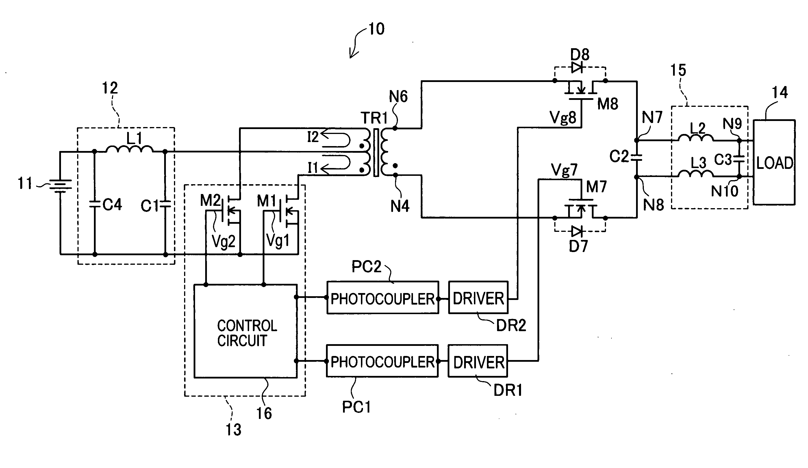
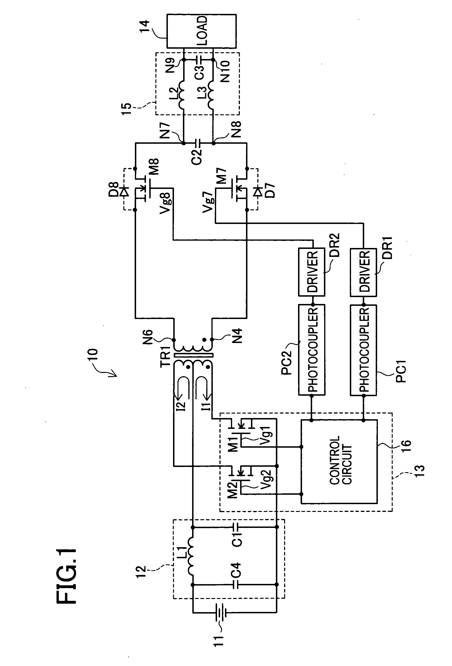
[0064] As heretofore described in detail, the DC / AC converter 10 of the first embodiment is configured such that when a current path for flowing an electric current in the forward direction of the body diode D8 is formed in the secondary side of the transformer TR1, a voltage component having plus polarity (on the basis of the node N4) is selected from AC voltages generated in the secondary winding of the transformer TR1 by this current path. Similarly, when a current path for flowing an electric current in the forward direction of the body diode D7 is formed in the secondary side of the transformer TR1, a voltage component having minus polarity (on the basis of the node N4) is selected from the AC voltages generated in the secondary winding of the transformer TR1 by this current path. Plus and minus polarities are alternately selected at the second frequency f2 (55 Hz), thereby enabling it to supply an AC voltage of the second frequency f2 to the load 14 through the AC output filte...

second embodiment

[0074] As heretofore described in detail, the DC / AC converter 10a of the second embodiment is configured such that the source terminals of the transistors M7, M8 are connected to a common connection so that a common driver circuit can be used for application of gate voltages. This contributes to simplification of the driver circuit for gate voltage application and therefore to a reduction in the number of parts. As a result, the circuit can be scaled down and cost reduction due to the reduction in the number of parts and increased reliability etc. can be achieved.

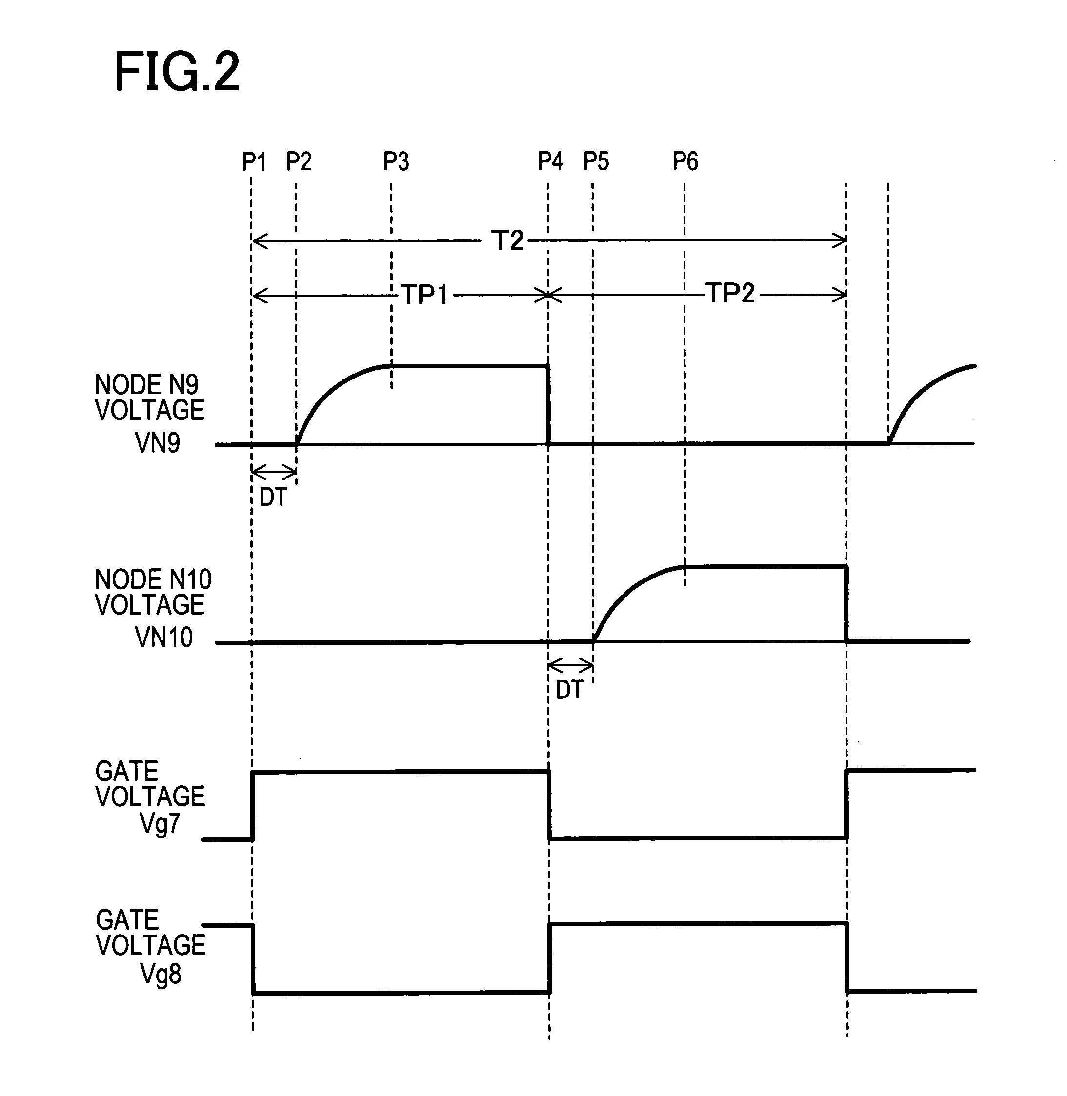
[0075] It is obvious that the invention is not necessarily limited to the particular embodiments shown herein and various changes and modifications may be made to the disclosed embodiments without departing from the spirit and scope of the invention. In the first embodiment, the soft start for switching of the transistors M1, M2 is performed whenever the transistors M7, M8 are switched at the second frequency f2 as shown in...


PUM


Abstract

A switching circuit 13 switches transistors M1, M2 at a first high frequency f1 (100 kHz). Thereby, a DC low voltage input is converted into an AC voltage having a high frequency of 100 kHz. A transformer TR1 insulation-transfers the AC voltage of 100 kHz outputted from the switching circuit 13. Transistors M7, M8 provided in the secondary side are formed such that the state where the transistor M7 is conductive whereas the transistor M8 is non-conductive and the state where the transistor M7 is non-conductive whereas the transistor M8 is conductive are alternately changed at a second frequency f2 (55 Hz). An AC output filter 15 outputs an AC voltage corresponding to a commercial AC power source of 55 Hz, 100V to supply to a load 14. In conversion from a DC voltage to an AC voltage by use of a transformer, simplified converting operation is employed so that the circuit can be scaled down and use of a small-sized transformer is realized.

Description

CROSS-REFERENCE TO RELATED APPLICATIONS [0001] This application is based upon and claims the benefit of priority from the prior Japanese Patent Application No. 2005-169276 filed on Jun. 9, 2005, the entirety of which is incorporated herein by reference. FIELD OF THE INVENTION [0002] The present invention relates to a DC / AC converter circuit and a DC / AC conversion method. More particularly, the present invention is directed to a DC / AC converter circuit and a DC / AC conversion method which involve a simple circuit configuration due to simple converting operation and realize use of a compact-sized transformer. BACKGROUND OF THE INVENTION [0003]FIG. 5 is a block diagram showing the configuration of an AC inverter for use in automobiles disclosed in Japanese Unexamined Patent Publication No. 2002-315351. As shown in FIG. 5, this AC inverter includes a DC input unit 121; a switching circuit 124; a transformer 125; a DC high-voltage rectifying circuit 126 (smoothing circuit); a driving circ...

Claims


Application Information

Patent Timeline
Patent Type & Authority Applications(United States)
IPC IPC(8): H02M3/335H02M7/48
CPCH02M7/4807
Inventor IIDA, TAKAHIDE
Owner TOYOTA IND CORP
Why Eureka
Try Eureka