Engine-mounted fan shroud and seal

a technology of engine-mounted fans and shrouds, which is applied in the direction of machines/engines, stators, liquid fuel engines, etc., can solve the problems of reducing the cooling effectiveness of fans, and achieve the effects of reducing the number of different parts, reducing fabrication and assembly time, and increasing the efficiency of engine-driven fans

Active Publication Date: 2006-12-14
GM GLOBAL TECH OPERATIONS LLC
View PDF12 Cites 7 Cited by
  • Summary
  • Abstract
  • Description
  • Claims
  • Application Information

AI Technical Summary

Benefits of technology

[0007] An advantage of an embodiment of the present invention is that the engine-mounted fan shroud is formed as an integral part, thus reducing the fabrication and assembly time, and reducing the number of different parts in the overall fan shroud assembly. Only a single mold, employing a two shot process, is required to fabricate this engine-mounted fan shroud, without any post mold processes required to affixed the components to one another.
[0008] Another advantage of an embodiment of the present invention is that, while the engine-mounted fan shroud is formed as an integral part, the shroud body and stators are made from a material having the required strength and stiffness properties to maintain their shape during vehicle operation while the bodyside seal is made from a material that is flexible enough to create and maintain a sealing contact with the body-mounted shroud. Thus, the increase in efficiency of the engine driven fan is still maintained by this new integral engine-mounted fan shroud.

Problems solved by technology

One concern with the airflow pattern generated by the fan is that the air will just recirculate, thus reducing the cooling effectiveness of the fan.
But all of these require the fabricating and handling of separate components—and some also require additional assembly steps—to create an engine-mounted fan shroud assembly.

Method used


Image

  • Engine-mounted fan shroud and seal
  • Engine-mounted fan shroud and seal
  • Engine-mounted fan shroud and seal

Examples


Embodiment Construction

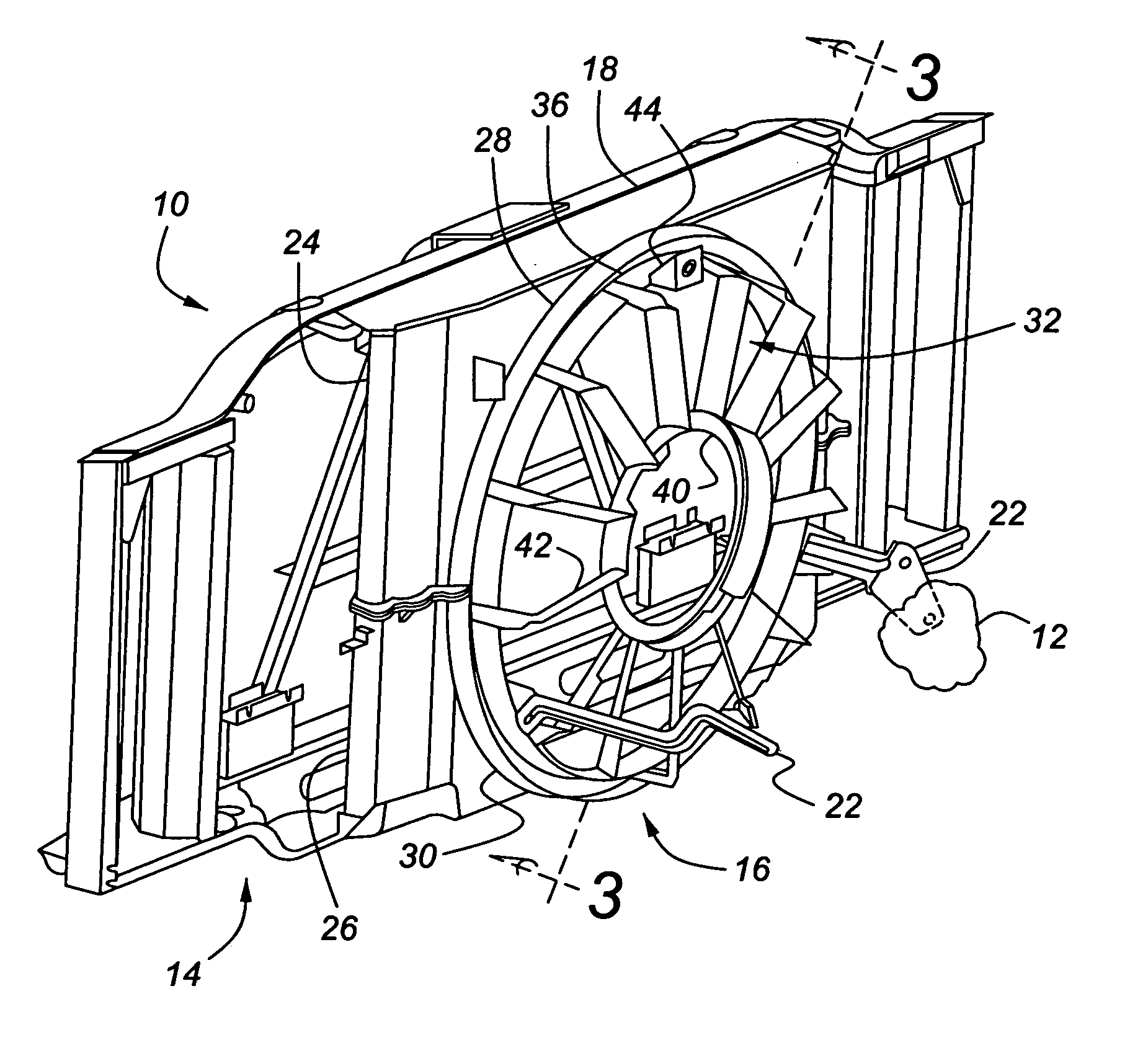
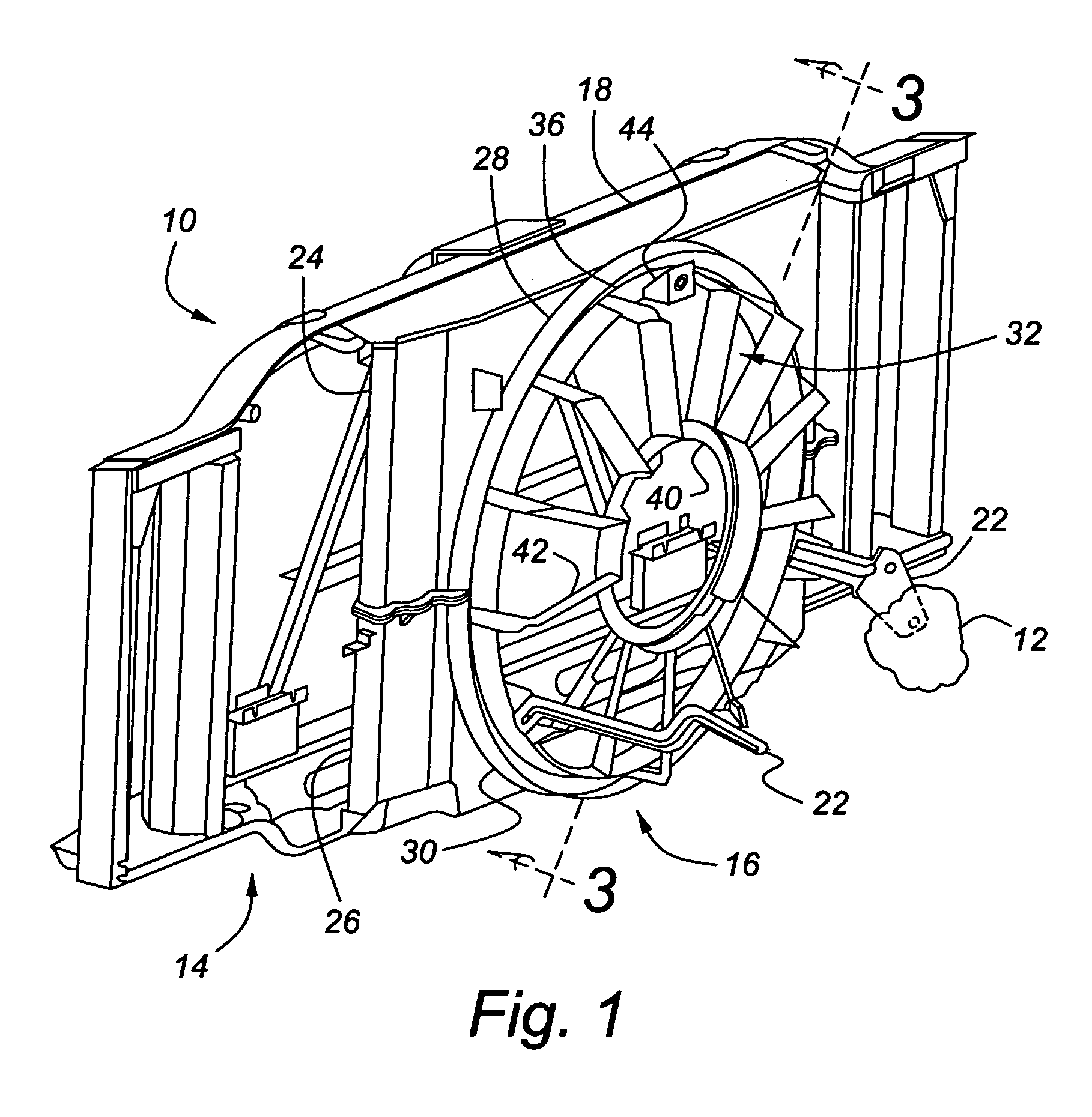
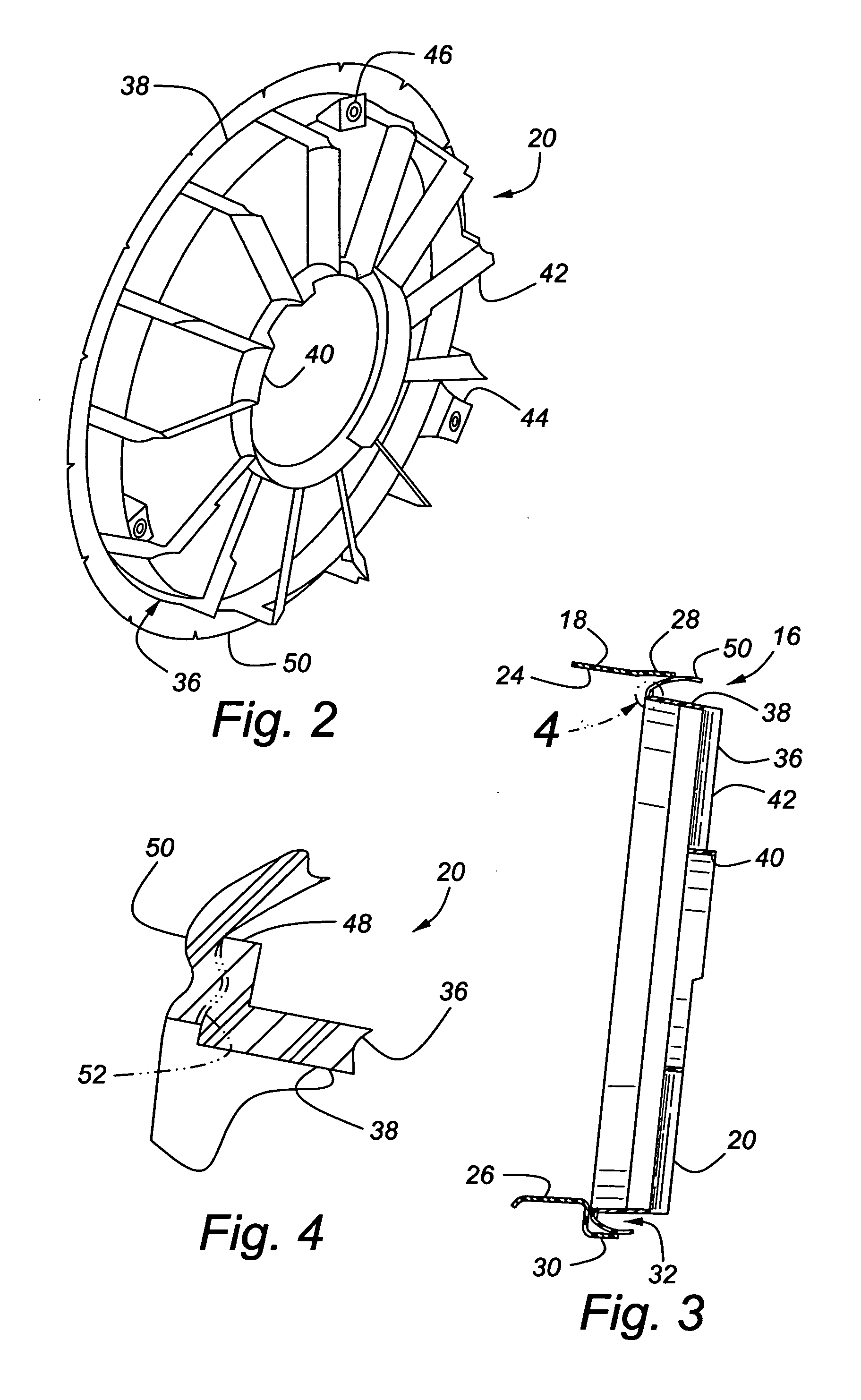
[0013]FIGS. 1-4 show components in an engine compartment, indicated generally at 10, with a portion of an engine, indicated generally at 12. A radiator (heat exchanger) support structure 14 mounts to the vehicle body (not shown). Heat exchangers (not shown), such as a radiator and condenser, mount to the radiator support structure 14. An engine driven fan (not shown) extends from the engine 12 toward the heat exchangers. The vehicle components discussed so far can be conventional and so will not be discussed further herein.

[0014] A fan shroud assembly 16 includes a body-mounted shroud 18, which is mounted to the radiator support structure 14, and an engine-mounted fan shroud 20, which is mounted to the engine 12, preferably to the engine block via three mounting brackets 22 (only two of three shown). The body-mounted shroud 18 has an upper shroud 24 that is connected to a lower shroud 26. The upper and lower shrouds 24, 26 each include a semi-cylindrical fan opening flange 28, 30, ...


PUM


Abstract

The invention concerns an engine-mounted fan shroud for use in a vehicle that has a shroud body supported by a vehicle engine, including an outer ring made of a first material having a first stiffness, and a bodyside seal extending from and being integral with the outer ring, with the bodyside seal being made of a second material having a second stiffness that is less than the first stiffness. The bodyside seal fits into and seals around a seal opening in a body-mounted shroud that is mounted to radiator support structure.

Description

BACKGROUND OF INVENTION [0001] The present invention relates to a vehicle having an engine-mounted fan shroud. [0002] For most automobiles and trucks driven by an internal combustion engine, a cooling fan is located adjacent to heat exchangers in an engine compartment and driven by the engine. This cooling fan ensures enough air flow to prevent overheating. The heat exchangers may be, for example, a radiator and a condenser for an air conditioning system, which are typically mounted, via support structure, to the body of the vehicle. One concern with the airflow pattern generated by the fan is that the air will just recirculate, thus reducing the cooling effectiveness of the fan. As a result, in some vehicles, fan shrouds are employed that encircle the fan close to the heat exchangers. [0003] Since there may be tolerances in the position of the heat exchangers relative to the engine, and the engine and heat exchangers may move somewhat relative to each other during vehicle operation...

Claims


Application Information

Patent Timeline
Patent Type & Authority Applications(United States)
IPC IPC(8): F01D11/08
CPCF04D29/668F04D29/526
Inventor ALEXANDER, JOSEPH H.TATROW, JEFFREY R.MUELLER, PAUL R.
Owner GM GLOBAL TECH OPERATIONS LLC
Why Eureka
Try Eureka