Intervertebral disc implant

a technology of intervertebral discs and implants, which is applied in the field of intervertebral disc implants, can solve the problems of compromising the normal interaction between the disc and adjacent vertebrae, affecting the patient's life, and affecting the patient's quality of life,

Inactive Publication Date: 2006-12-14
PERUMALA CORP
View PDF49 Cites 49 Cited by
  • Summary
  • Abstract
  • Description
  • Claims
  • Application Information

AI Technical Summary

Benefits of technology

[0017] In another aspect, the present invention provides a method of mimicking the function of the intervertebral disc of the intact spinal column after removal of a portion or all of the intervertebral disc from between the two adjacent vertebrae comprising the steps of inserting a resilient body having a height greater than its width and a cavity formed therein with a key received in the cavity into the intervertebral disc space with the height of the body oriented substantially parallel to the longitudinal axis of the spinal column, removing the key from the cavity in the body after the body is inserted into the intervertebral disc space, and inserting a frame part way into the cavity in the body, the frame comprising first and second arms arms connected by a bridge at one end for providing resistance to flexion and / or extension of the spinal column, and filling the portion of the cavity in the body into which the frame does not extend with a hydrogel.

Problems solved by technology

Treatment of the damaged intervertebral disc, especially in the cervical and / or lumbar region of the spine, continues to be a challenging field of medicine.
In this process, all or a portion of the intervertebral disc is removed, leaving a defect that may bother the patient throughout the rest of their life and compromising the normal interaction between disc and adjacent vertebrae.
Diskectomy with fusion is not ideal because the replaced bone does not have the function of the cartilaginous tissue of the disc, i.e. no cushioning effect, and has complications because of several factors.
First, conventional bone plugs used to pack the disc space do not conform to the space of the disc because the disc bulges maximally in the center while the bone plug is generally cylindrically shaped and the disc space is wider in the middle and narrower at its anterior and posterior ends.
Second, access to the disc is from the side of the dorsal spine of the adjacent vertebrae, leaving a space that is “off-center” relative to the bodies of the adjacent vertebrae such that the stability of the implant is even more problematical than might be apparent from the limited contact resulting from the shape of the intervertebral space.
Another complication is the possibility of infection or other conditions that may require removal of the implant.
Also, if the bone pieces do not fuse, they may eventually extrude out of the disc space, pressuring the nerve roots.
The most significant disadvantages of fusion, however, is that it eliminates all motion at the joint between the two vertebrae as well as the shock-absorbing / cushioning function of the disc.
Various prosthetic disc plugs, or implants, are disclosed in the art, but all are characterized by limitations of not conforming to the shape of the disc space, lack of stability when inserted off-center, inability to be removed, or other disadvantages.
However, because that device is cylindrical in shape such that the only contact points between the device and the vertebral bodies are at the front and back of the disc space, creating increased likelihood of instability, that device is generally unsuitable for use after partial diskectomy.
The utility of such devices is also limited by a number of disadvantages, in particular, the same lack of cushioning described above in connection with prior art disc plugs and implants.
Further, those implants and prostheses that attempt to address this cushioning problem have generally failed because they are not capable of supporting the load imposed upon them by the active post-surgical patient.
Further, many prior implants and prostheses require removal of the disc.

Method used


Image

  • Intervertebral disc implant
  • Intervertebral disc implant

Examples


Embodiment Construction

)

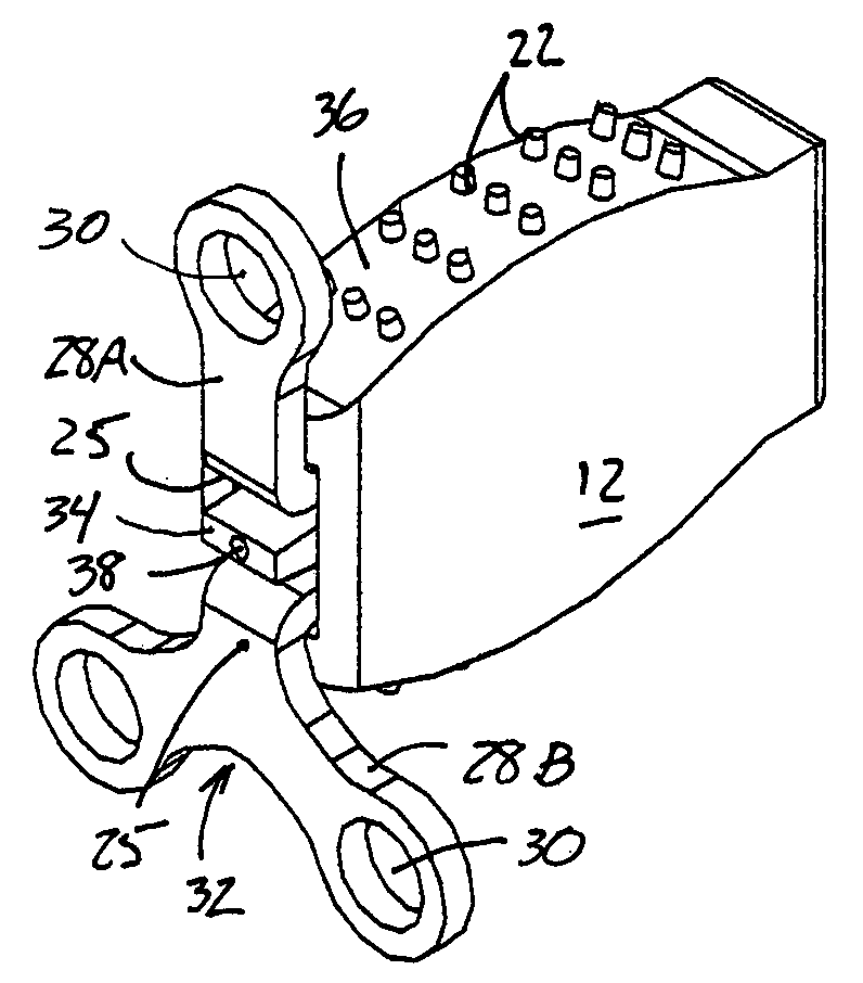
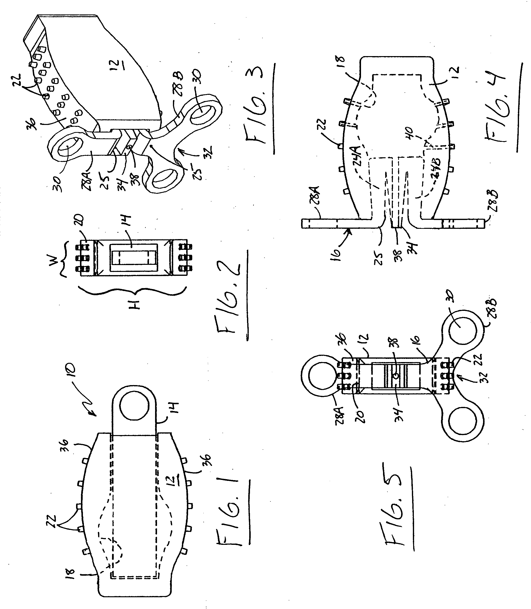
[0023] In more detail, FIG. 1 shows a presently preferred embodiment of an intervertebral disc implant constructed in accordance with the teachings of the present invention at reference numeral 10. Disc implant 10 is comprised of three components, each described in more detail below, implant body 12, key 14, and frame 16. Body 12 is preferably molded from a resilient, polymeric material. Although not limited to these materials, in the preferred embodiment, body 12 is molded from a biocompatible, viscoelastic polymer such as silicone, a urethane such as a polycarbonate urethane, or a polyurethane. As shown in FIGS. 1, 2, and 3, the body 12 is molded with a profile that approximates the shape of the normal intervertebral disc space with a height H greater than the width W (see FIG. 2); the top and bottom surfaces 36 of body 12 are arched so that the height of body 12 is greater in the center than at its ends. This shape of body 12 is referred to as being biconvex, e.g., both the top ...


PUM

PropertyMeasurementUnit
tensionaaaaaaaaaa
angleaaaaaaaaaa
heightaaaaaaaaaa

Abstract

An intervertebral disc implant having a body with a greater height than width comprised of a resilient material and an elongate cavity for receiving a key to maintain the spacing between the vertebrae adjacent an intervertebral disc when implanted into the space from which a portion of the disc is removed. To distribute and cushion against compression loads, and to mimic the normal kinematics of the intact, healthy intervertebral disc, the key is removed after the body is implanted into the disc space and a frame that both provides resistance to compression and tension loads and translates the axis of rotation of the spinal column anteriorally and posteriorally as the patient bends and rotates is inserted into the cavity in the implant body. The frame does not extend all the way into the cavity in the body and the portion of the cavity into which the frame does not extend is filled with a hydrogel.

Description

[0001] This application in a continuation-in-part of co-pending applications Ser. No. 11 / 246,961, filed Oct. 7, 2005, entitled TOTAL ARTIFICIAL INTERVERTEBRAL DISC, Ser. No. 11 / 195,890, filed Aug. 2, 2005, entitled TOTAL ARTIFICIAL DISC, International Application No. PCT / US2005 / 009323, filed Mar. 19, 2005, entitled ROTATING, LOCKING, SPRING-LOADED ARTIFICIAL DISK, and Ser. No. 10 / 804,895, filed Mar. 19, 2004, entitled ROTATING, LOCKING, SPRING-LOADED ARTIFICIAL DISK.BACKGROUND OF THE INVENTION [0002] The present invention relates to an intervertebral disc implant for stabilizing two adjacent vertebrae that maintains the functions of the normal, healthy disc. More specifically, the present invention relates to a rectangularly-shaped disc implant that is expanded in the middle portion that is used as an alternative to spinal fusion. [0003] Treatment of the damaged intervertebral disc, especially in the cervical and / or lumbar region of the spine, continues to be a challenging field of ...

Claims


Application Information

Patent Timeline
Patent Type & Authority Applications(United States)
IPC IPC(8): A61F2/44
CPCA61F2/3094A61F2310/00796A61F2/442A61F2002/30069A61F2002/30075A61F2002/30331A61F2002/30426A61F2002/30546A61F2002/30563A61F2002/30566A61F2002/30571A61F2002/30578A61F2002/30579A61F2002/30581A61F2002/30601A61F2002/3067A61F2002/30795A61F2002/30841A61F2002/449A61F2002/4495A61F2002/482A61F2210/0061A61F2220/0025A61F2220/0033A61F2250/0002A61F2250/0012A61F2310/00011A61F2310/00023A61F2310/00029A61F2310/00161A61F2310/00407A61F2/441A61F2/482
Inventor PISHARODI, MADHAVAN
Owner PERUMALA CORP
Why Eureka
Try Eureka