Evaluating the leaktightness of a device for storing fuel gas under high pressure

Active Publication Date: 2006-12-21
GDF SUEZ SA
View PDF11 Cites 18 Cited by
  • Summary
  • Abstract
  • Description
  • Claims
  • Application Information

AI Technical Summary

Benefits of technology

[0006] The present invention seeks to remedy the drawbacks of the prior art and to make it possible to evaluate the leaktightness of a high pressure fuel gas storage device in a manner that is simple and inexpens

Problems solved by technology

Such leak testing systems are difficult to use in simple manner since it is necessary either for the tank to be emptied

Method used


Image

  • Evaluating the leaktightness of a device for storing fuel gas under high pressure
  • Evaluating the leaktightness of a device for storing fuel gas under high pressure
  • Evaluating the leaktightness of a device for storing fuel gas under high pressure

Examples


Embodiment Construction

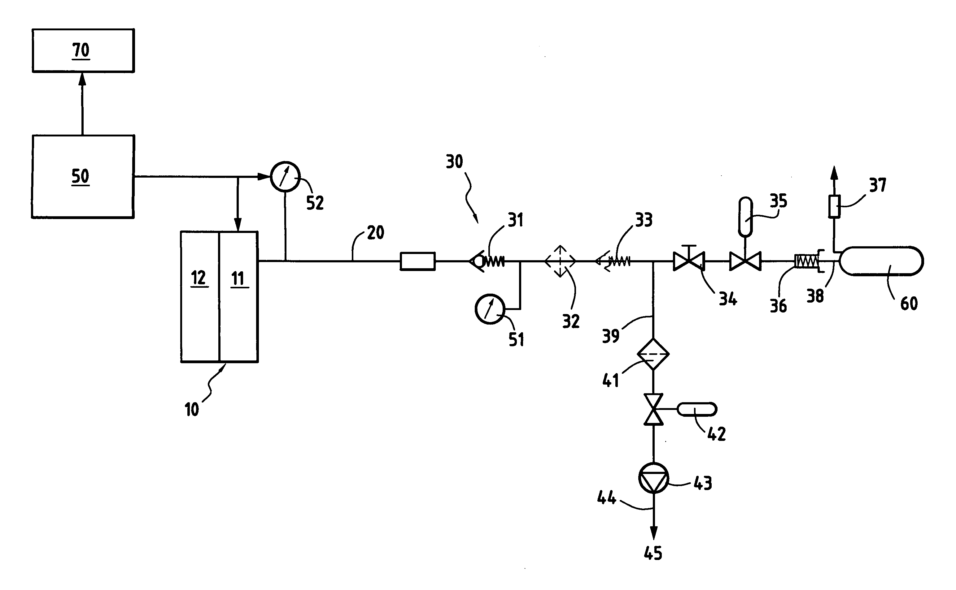
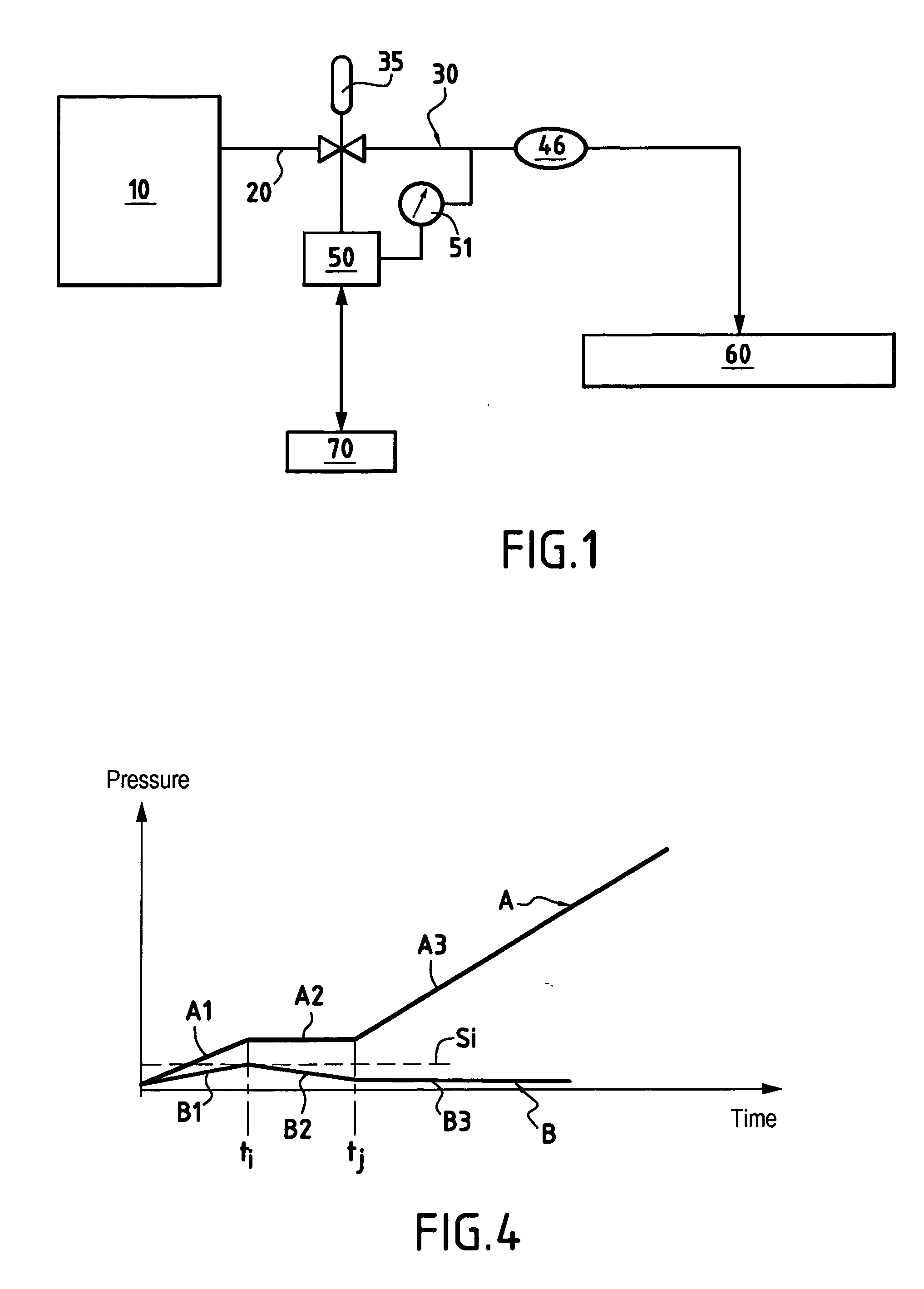
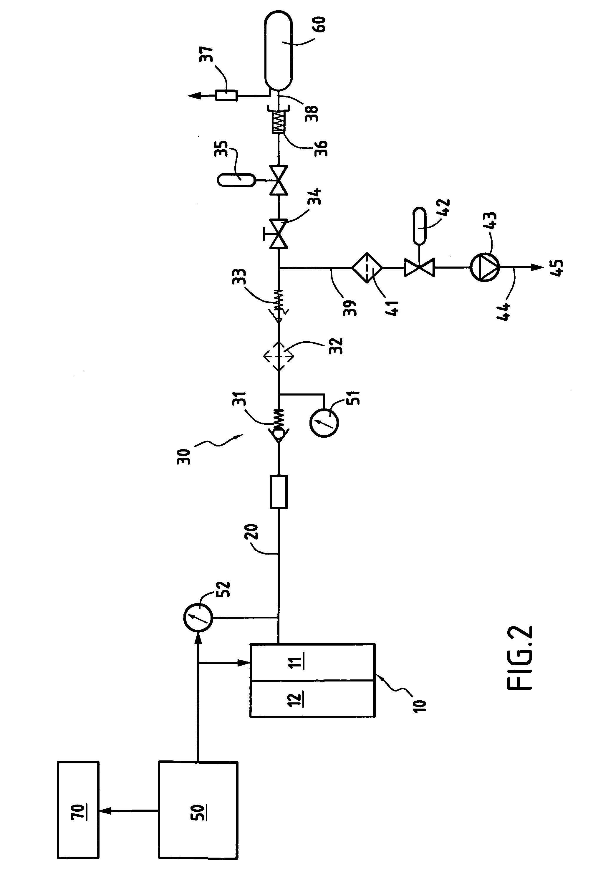
[0030]FIG. 1 is a general diagram showing the principle of a leak diagnosis system in accordance with the invention for evaluating the leaktightness of devices (pipework, tanks) for storing a gaseous fuel under high pressure such as compressed natural gas (CNG) which is used in vehicles and is then referred to as natural gas for vehicles (NGV).

[0031] Compressed natural gas is available in filling stations 10 having terminals provided with flexible filler hoses 20 to which users can make a connection in order to fill a tank such as 60.

[0032] In the invention, one or more tanks 60 such as vehicle tanks, associated with pipework 30 suitable for connection to a filler hose 20, itself connected to a filling station 10, co-operate with a system for diagnosing leaktightness that comprises essentially a pressure gauge 51, processor circuits 50, such as a microcomputer, and a display unit 70 that may form part of the microcomputer or that may constitute a unit that is independent from the ...


PUM


Abstract

The system for evaluating leaktightness is applied to a gas storage device for storing high pressure fuel gas delivered from a filling station via a filler hose connected to the gas storage device, itself comprising pipework and at least one tank, together with at least one check valve disposed between the pipework and the tank. The system comprises a pressure-measuring device that is suitable for connection to the filler hose or to the pipework, a processor device for processing values measured by the pressure-measuring device, and a display device for displaying information supplied by the processor device. The device for processing values measured by the pressure-measuring device includes a device for controlling filling and for suspending filling of the fuel gas storage device from the filling station, a device for controlling the filling flowing rate, a clock, and a unit for comparing the measured pressure relative to predetermined thresholds Si during periods in which filling is suspended.

Description

FIELD OF THE INVENTION [0001] The present invention relates to a method and a system for evaluating the leaktightness of a gas storage device for storing fuel gas under high pressure that is delivered from a filling station via a filler hose that is connected to the gas storage device, itself comprising pipework and at least one tank. [0002] The invention also relates in particular to filling tanks of fuel natural gas and to leak testing on-board high-pressure systems in which the pressure may be about 200 bars, for example. STATE OF THE PRIOR ART [0003] Various systems are already known for leak testing tanks containing non-pressurized liquid fuel (such as, for example, diesel or gasoline). [0004] Under such circumstances, the operation is performed on a vehicle under maintenance and requires certain elements to be previously disconnected and also requires a special connection element to be used in order to ensure a leaktight connection between the filler endpiece and a source of i...

Claims


Application Information

Patent Timeline
IPC IPC(8): G01M3/04G01M3/28
CPCG01M3/2815G01M3/3236G01M3/2892
Inventor COURRIEU, OLIVIER
Owner GDF SUEZ SA
Why Eureka
Try Eureka