Pressure sensing device with test circuit

a pressure sensing device and test circuit technology, applied in the direction of valve operating means/release devices, applications, diagnostic recording/measuring, etc., can solve the problems of difficult to test the pressure sensing device prior to use of the same, and the test circuitry of such pressure sensing devices can be fairly expensive, so as to achieve convenient testing, convenient use, and convenient testing.

Inactive Publication Date: 2006-12-21
SALTER LABS LLC
View PDF0 Cites 12 Cited by
  • Summary
  • Abstract
  • Description
  • Claims
  • Application Information

AI Technical Summary

Benefits of technology

[0006] A further object of the present invention is to provide a pressure sensing device which can be powered by a solar cell to eliminate dependency upon a battery for powering the pressure sensing device.
[0007] Yet another object of the present invention is to provide test circuitry in which the integrity of all of the internal circuitry of the pressure sensing device can be quickly and conveniently checked, by utilizing an internal battery powered circuit, to insure that there is adequate electrical conductivity for all of the internal circuitry and that none of the internal circuits is open, e.g., no electrical short is contained in any of the internal circuits.
[0008] A still further object of the present invention is to provide a piezoelectric crystal or piezo transducer within the test circuitry, for solely powering the test circuitry, to eliminate the need for a battery powering the test circuitry of the pressure sensing device when checking the electrical conductivity of the electrical leads.
[0009] Still a further object of the present invention is to provide a strain gauge arrangement which eliminates the need for utilizing a battery for powering the test circuitry, to insure that there is adequate electrical conductivity for all of the internal circuitry and that none of the internal circuits is open, e.g., no electrical short is contained in any of the internal circuits.
[0010] Yet another object of the present invention is to color code each pair of electrical leads, for each internal circuit of the pressure sensing device, to facilitate quick and accurate identification of the same. Preferably the pair of electrical leads, electrically coupled to the respiratory airflow detection circuit, are color coded a first color scheme, such as blue, red, yellow, black, grey, green, etc., which matches the color coding scheme of the airflow Hi / Lo switch for the respiratory airflow detection circuit and / or an area or border around the airflow Hi / Lo switch, while a second pair of electrical leads, electrically coupled to the respiratory snore detection circuit, are color coded a different second color scheme, such as blue, red, yellow, black, grey, green, etc., which matches the color coding scheme of the snore Hi / Lo switch for the respiratory snore detection circuit and / or an area or border around the snore Hi / Lo switch to facilitate the ease of use by an end user.
[0011] Another object of the present invention is to facilitate ease of connection of a nasal cannula to the pressure sensing device whereby the pressure sensing device remains flat on a support surface, such as a table, night stand, counter, etc., to facilitate actuation or switching of the airflow and snore Hi / Lo switches, located on the top surface of the pressure sensing device, in a stable manner for controlling operation of the respiratory airflow detection circuits and the respiratory snore detection circuitry.

Problems solved by technology

Due to the relatively small voltage that is utilized by the pressure sensing device, e.g., the pressure sensing device typically operates on millivolts, and due to the fact that noise is typically generated in and by such pressure sensing devices, the test circuitry for such pressure sensing devices can be fairly expensive, e.g., costing hundreds of dollars or so.
In addition, conventional test circuitry typically is completely separate from the pressure sensing device and this leads to further difficulties such as the test circuitry being either misplaced, lost, may have insufficient electrical power, etc., thereby rendering it difficult to test the pressure sensing device prior to use of the same.

Method used


Image

  • Pressure sensing device with test circuit
  • Pressure sensing device with test circuit
  • Pressure sensing device with test circuit

Examples


Embodiment Construction

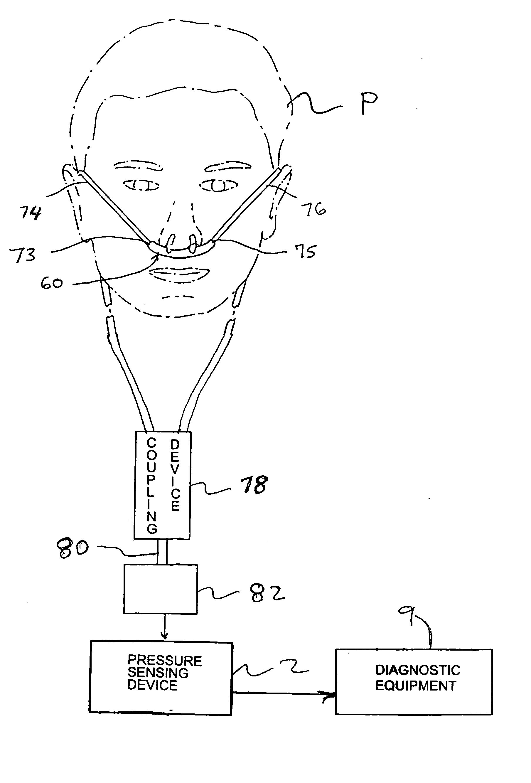
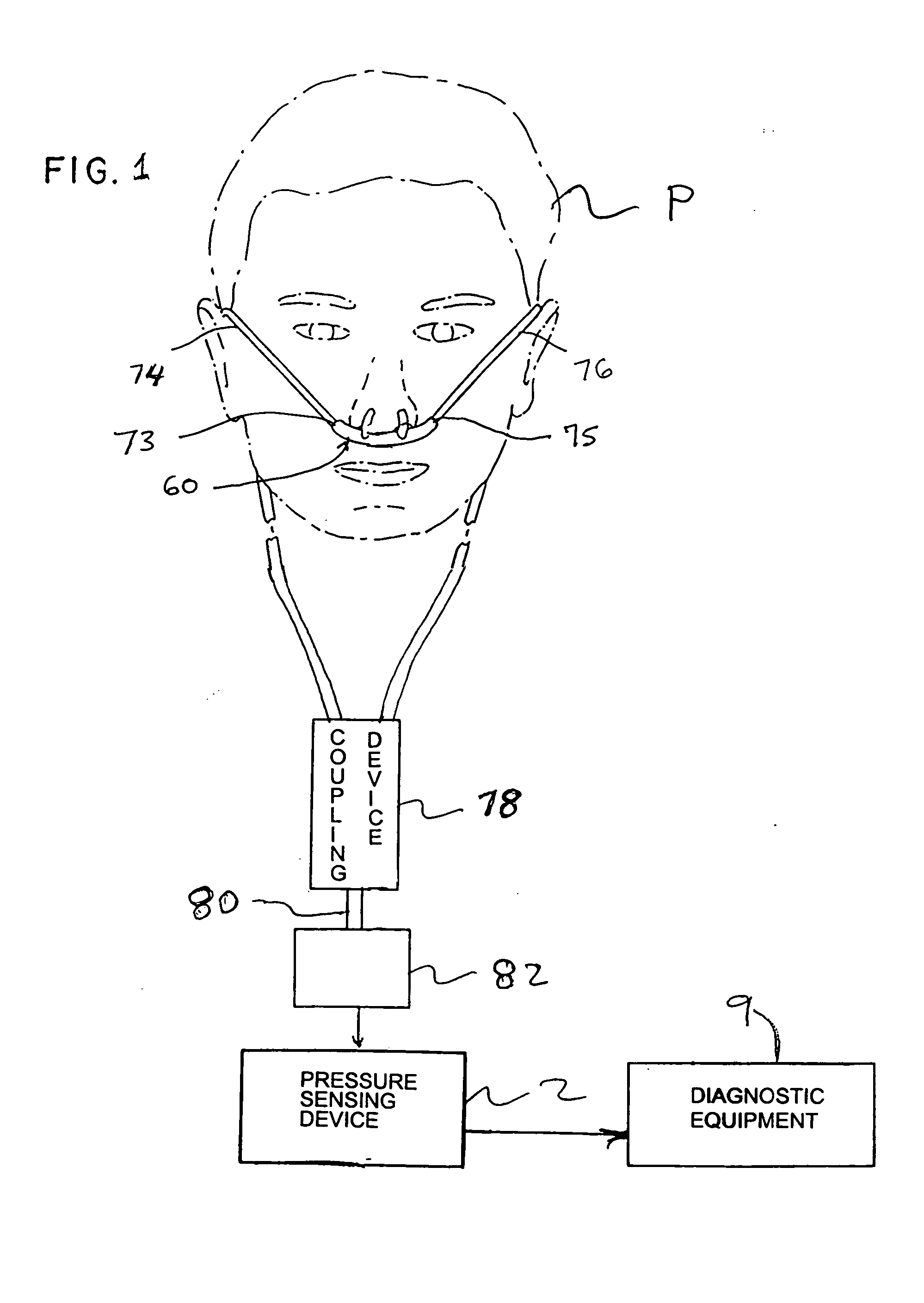
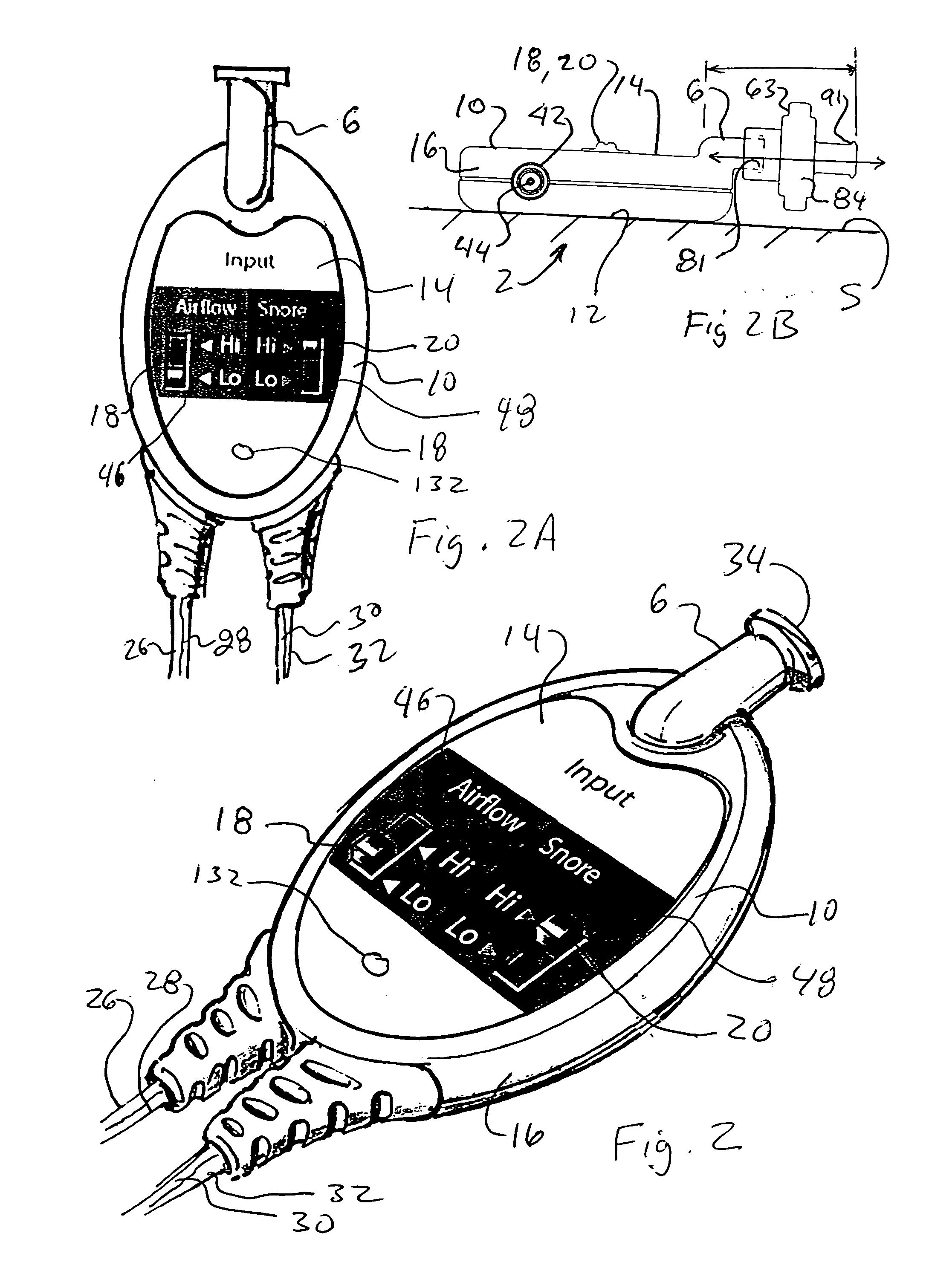
[0038] Turning now to FIGS. 1-5, a detailed description concerning a first embodiment of the pressure sensing device 2 of the present invention will now be provided. The pressure sensing device 2 of the present invention is generally a two output channel device which can be used to acquire respiratory (low) air pressure wave information and respiratory (low) airflow information (both of which are herein after collectively referred to as “breathing information 4”) via a conventional nasal cannula 60 worn by a patient P during a sleep diagnostic session or some other patient monitoring session. The nasal cannula 60 has a pair of spaced apart nares 65, 67 and preferably at least one or possibly a spaced apart mouthpiece lumens 69, 69′ to facilitate detection of respiratory air pressure waves and / or respiratory airflow in the event that the patient P breathes through his or her mouth. The nasal cannula 60 collects or acquires the breathing information 4, generated by breathing and / or sn...


PUM


Abstract

A pressure sensing device for coupling to a cannula and receiving respiratory breathing information from a patient to be monitored. The pressure sensing device comprising an exterior housing accommodating a snore detection circuit which processes information and outputs a signal indicative; an airflow detection circuit which processes information and outputs a signal indicative thereof; and an internal test circuit for testing an integrity of the airflow and snore detection circuits prior to use of the pressure sensing device to ensure that both circuits are operational. An input port for pressure sensing device extends from the housing of the pressure sensing device so as to space a connector, for the cannula, a sufficient distance away from the bottom surface whereby the bottom surface will always remain flush with and in constant and continuous intimate contact with a support surface for the pressure sensing device.

Description

FIELD OF THE INVENTION [0001] The present invention relates to a pressure sensing device for measuring respiratory air wave and airflow information during a sleep diagnostic session and processing the acquired air wave and airflow breathing information for input to conventional polysomnography equipment. To facilitate ease of use, the pressure sensing device is equipped with an internal test circuit which allows testing of the circuitry of the pressure sensing device prior to use of the same. BACKGROUND OF THE INVENTION [0002] A pressure sensing device is currently available from Pro-Tech Services, Inc. of Mukilteo, Wash. This pressure sensing device is used during a sleep diagnostic session to detect changes in respiratory air pressure and / or airflow to confirm whether or not a patient is breathing and to gather other breathing information from the patient. However, before this, as well as other, pressure sensing devices can be utilized during a sleep diagnostic session, it is gene...

Claims


Application Information

Patent Timeline
Patent Type & Authority Applications(United States)
IPC IPC(8): A61M16/00A62B7/10
CPCA61B5/087A61M2016/0027A61M2016/0021A61M16/0666A61M16/1065
Inventor CHUA, JAMESADRIANCE, KYLEVO, PHUOC H.
Owner SALTER LABS LLC
Why Eureka
Try Eureka