
Calibration standard

Active Publication Date: 2006-12-21
IMMOBILIENGESELLSCHAFT HELMUT FISCHER GMBH & CO KG
View PDF4 Cites 6 Cited by
  • Summary
  • Abstract
  • Description
  • Claims
  • Application Information

AI Technical Summary

Benefits of technology

[0005] Accordingly, this invention is based on the objective of providing a calibration standard which is simple to produce, having a high precision and repeating accuracy for the calibration of a device.
[0006] This problem is solved by a calibration standard in which the standard is permanently provided by means of plating by rubbing on the carrier layer. Due to plating by rubbing the standard on the carrier layer, it will be possible to provide—without bonding agents or other additives—a connection between the standard and the carrier layer by adhesion. After plating by rubbing and positioning of the standard on the carrier layer, a type of cold welding will result with an increasing duration of time. This connection ensures a secure and plane-parallel configuration of the standard on the carrier layer. At the same time, a high-precision design of the calibration standard is achieved since no additional materials are intended between the standard and the carrier layer which might result in buckling or warping of the surface of the standard versus the carrier layer.
[0007] According to an advantageous development of the invention, it is provided that the standard is positioned on the carrier layer by means of displacement movements with minor pressure. This can ensure that the layer of air between the bearing surface of the standard and a measuring surface of the carrier layer will be entirely displaced, and a direct adjacency of the bearing surface of the standard to the measuring surface of the carrier layer will be provided.
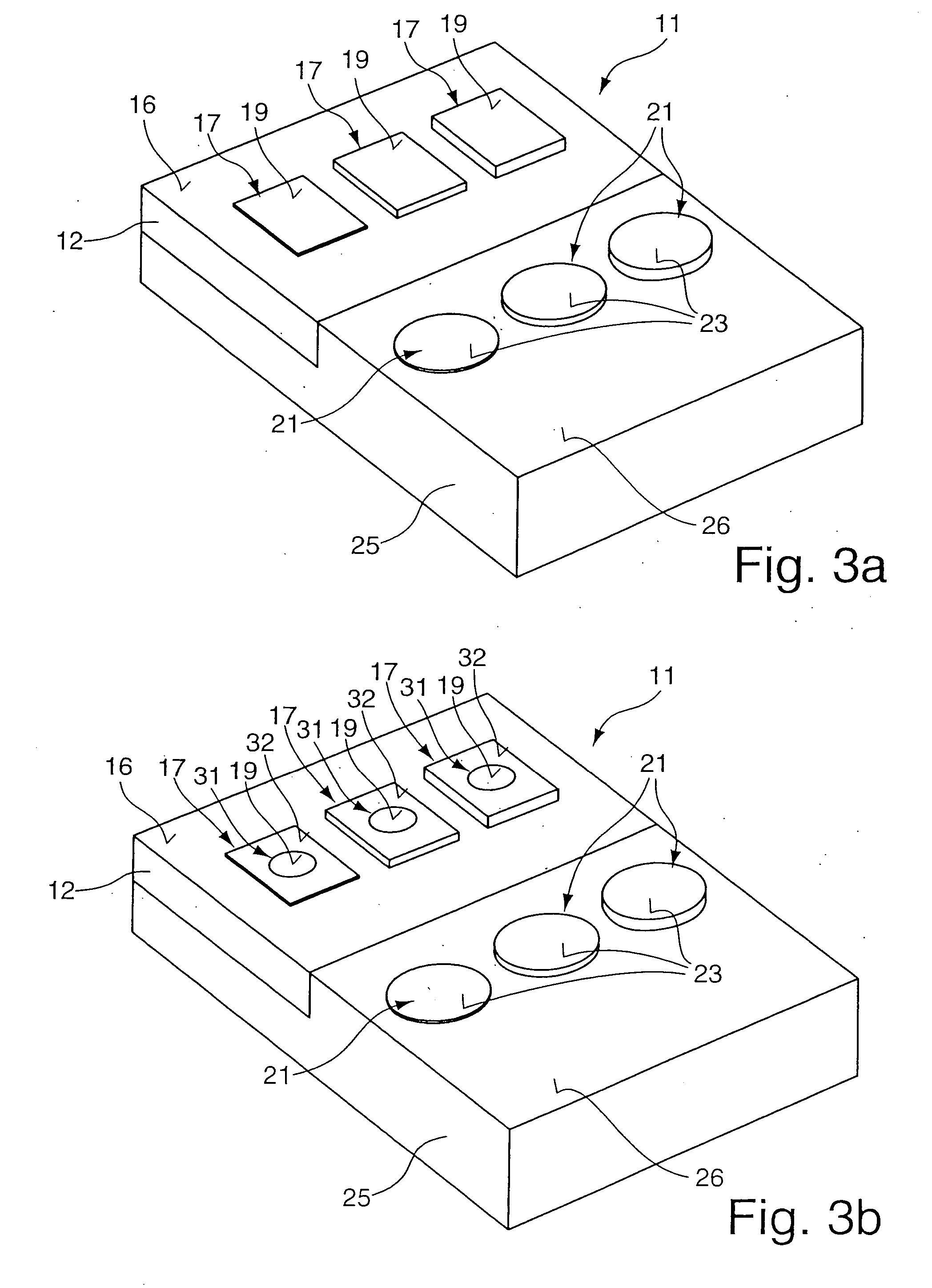
[0011] According to another advantageous embodiment of the invention, it is provided that an auxiliary pole is allocated to the standard. This auxiliary pole is provided on a basic body at a pre-determined distance to the standard so that a device for measuring the thickness of thin layers—especially a manual measuring instrument—can be simply and safely calibrated with a base point or contact point or, respectively, an abutment.
[0012] Advantageously, it is provided that a carrier layer taking up several standards is positionable on a bearing surface on the basic body, with the bearing surface on the basic body being designed plane-parallel with the auxiliary pole. Thus, an exact alignment of the measuring surfaces of the carrier layer and the standards and the bearing surfaces on the basic body can be enabled.
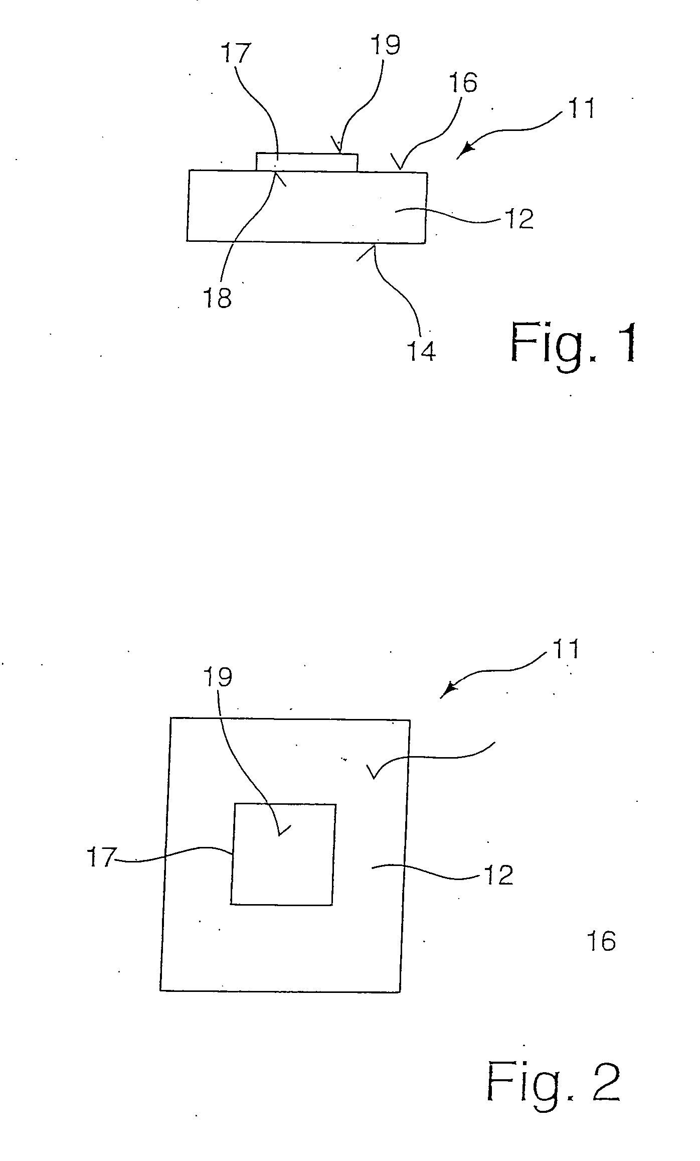
[0015] It is preferably provided that the standard is surrounded by a frame which preferably directly borders on the measuring surface of the standard. This embodiment has the advantage that the standard—in its planar extension—can be designed very small for setting on a sensor element of the measuring probe and that the following frame presents an enlargement of the contact surface for a probe bush of the measuring probe. The sensor element of the measuring probe is mostly kept movably in a probe bush. It will thus be rendered possible that the standard can be designed very small in its size and costs can thus be saved, with the supplementary frame having the same function as with a large-surface standard.

Problems solved by technology

After plating by rubbing and positioning of the standard on the carrier layer, a type of cold welding will result with an increasing duration of time.

Method used


Image

  • Calibration standard
  • Calibration standard
  • Calibration standard

Examples


Embodiment Construction

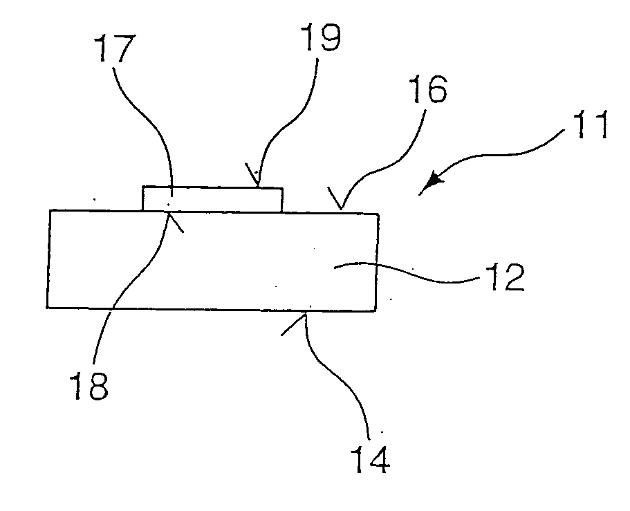
[0024]FIG. 1 presents diagrammatically the calibration standard 11 according to the invention. It comprises a carrier layer 12 with a bearing surface 14 for positioning the calibration standard 11 on a measuring table or a work area. On the opposite side, a measuring surface 16 of the carrier layer 12 is provided which is produced plane-parallel with the bearing surface 14. This measuring surface 16 is preferably high-gloss polished. On this measuring surface 16, the standard 17 is provided. It rests with one bearing surface 18 on the measuring surface 16. On the opposite side, one measuring surface 19 of the standard 17 is provided, with the bearing surface 18 being aligned plane-parallel with the measuring surface 19.

[0025] The carrier layer 12 comprises a basic material, for example steel and iron for the magnetic induction layer thickness measuring method and a non-ferromagnetic basic material, e.g. non-magnetic steel, aluminum and their alloys for the layer thickness measureme...


PUM


Abstract

The invention relates to a calibration standard, especially for the calibration of devices for the non-destructive measurement of the thickness of thin layers, with a carrier layer (12) consisting of a basic material and a standard (17) applied on the carrier layer (12), said standard having the thickness of the layer to be measured at which the device is to be calibrated, with the carrier layer (12) comprising a plane-parallel measuring surface (16) to its bearing surface (14), that the standard (17) comprises a bearing surface (18) plane-parallel with its measuring surface (19) for bearing on the measuring surface (16) of the carrier layer (12), and that the standard (17) is permanently provided on the carrier layer (12) by means of plating by rubbing.

Description

BACKGROUND OF THE INVENTION [0001] This invention relates to a calibration standard, especially for the calibration of devices for the non-destructive measurement of the thickness of thin layers with a carrier layer of a basic material and a standard applied on the carrier layer, said standard having the thickness of the layer to be measured at which the device is to be calibrated. [0002] For the non-destructive measurement of the thickness of thin layers by a magnetic induction method or an eddy current method depending on the basic material, it is necessary that—after a standardization—the devices are calibrated to the corresponding measuring task. By means of the calibration, a difference between nominal and actual values is established. This difference will be corrected, with the device being calibrated to the measuring task. [0003] For the correction of the difference between nominal and actual value, a measurement by means of the calibration standard is performed. To start wit...

Claims


Application Information

Patent Timeline
IPC IPC(8): G21K7/00
CPCG01B7/105G01B21/042G01B15/02G01D18/00G01N23/00
Inventor FISCHER, HELMUT
Owner IMMOBILIENGESELLSCHAFT HELMUT FISCHER GMBH & CO KG
Learn More