Optical data recording method

a technology of optical data and recording film, applied in the field of optical data recording film, can solve the problems of serious degradation of signal quality, inability to apply predetermined quantity of heat to the recording film of the optical disc, and dull edge and falling edge of pulses in luminous waveforms

Inactive Publication Date: 2006-12-21
PANASONIC CORP
View PDF19 Cites 22 Cited by
  • Summary
  • Abstract
  • Description
  • Claims
  • Application Information

AI Technical Summary

Problems solved by technology

Thus, there arises a problem that undeleted data remains during direct overwriting and signal crosstalk occurs between tracks, which results in the seriously degradation of the signal quality.
However, according to this conventional method, when a speed for recording data is increased, for example, when data is recorded on an optical disc at a high transfer rate, since the response speed of a laser diode is not ideally high, the rising edge and the falling edge of a pulse becomes dull in a luminous waveform.
Thus, a predetermined quantity of heat cannot be applied to the recording film of the optical disc.
Particularly since the multi-pulse train has a pulse width of about 0.25 to 0.75 T, for example, it becomes difficult to generate a pulse of a sinusoidal wave in some rising times and falling times of a laser.
Hence, a correct mark cannot be formed.

Method used


Image

  • Optical data recording method
  • Optical data recording method
  • Optical data recording method

Examples


embodiment 1

[0069]FIG. 3 is a block diagram showing Embodiment 1 of a data recording device according to the present invention. As shown in FIG. 3, a data recording device 100 comprises a spindle motor 102, an optical head 103, a light beam control section 104, a servo section 105, a reproduction binarizing section 106, a digital signal processing section 107, a recording compensating section 108, and a CPU 109. The light beam control section 104 and the recording compensating section 108 form a recording pulse train generating section.

[0070] An optical disc 101 is placed on the spindle motor 102 and the spindle motor 102 rotates the optical disc 101. The optical disc 101 has one or more tracks for recording data. The tracks are shaped like spirals or concentric circles. The optical disc 101 has a recording film melted by heating. When a light beam of a semiconductor laser is emitted which is modulated based on data to be recorded, a phase change occurs on a part irradiated with the light beam...

embodiment 2

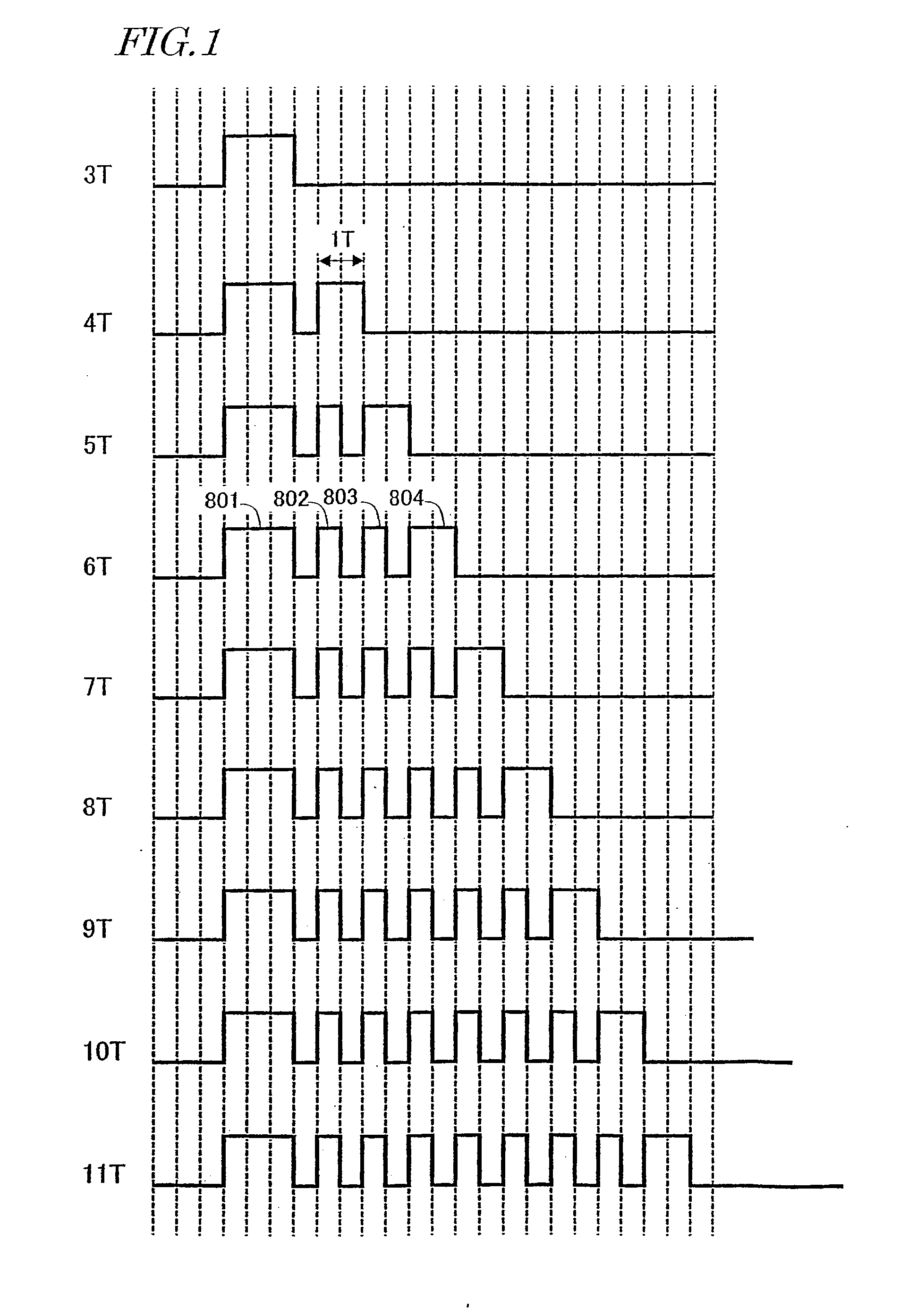
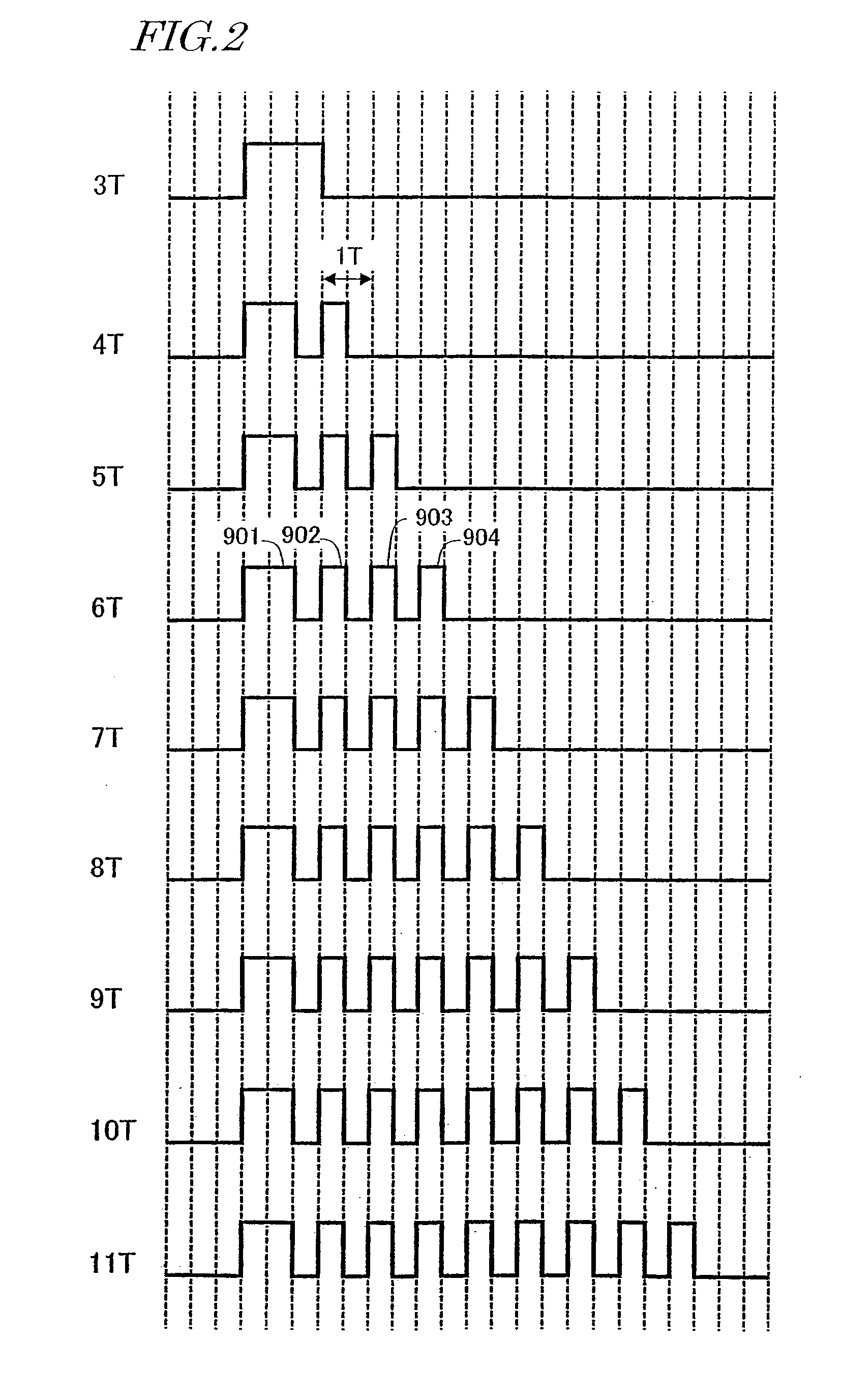
[0141] As described in Embodiment 1, by equalizing the number of pulses in each multi-pulse train of recording pulse trains 2 nT and (2n+1)T or recording pulse trains (2n−1)T and 2 nT, the two recording pulse trains may be different from each other in laser irradiation power. This is because a duty of a mark / space or an average value is different between the multi-pulse trains.

[0142]FIGS. 18A and 18B show recording marks and reproduction signals obtained from the formed recording marks. The recording marks are formed by a recording pulse train 2 for forming a mark 9 T of FIG. 10 and a recording pulse train 8 for forming a mark 10 T.

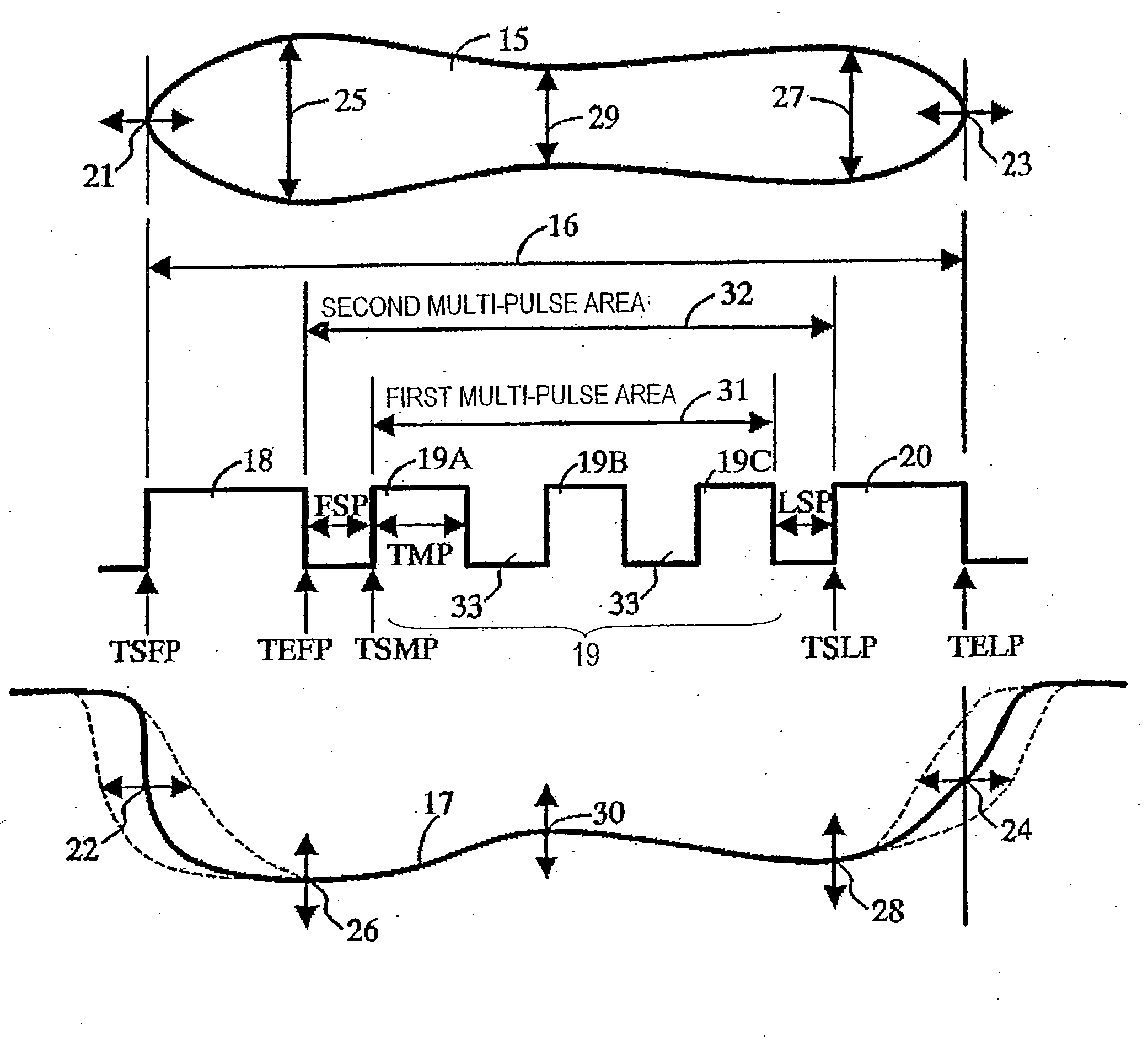
[0143] As shown in FIG. 18A, in the recording pulse train 2, a first pulse 9 and a last pulse 10 each have a pulse width of 1 T and supplies mark forming thermal energy suitable for a recording film of an optical disc. Thus, a recording mark 4 to be formed has an almost even width and a reproduction signal 6 is almost shaped like a trapezoid with a mark...


PUM

PropertyMeasurementUnit
phaseaaaaaaaaaa
temperatureaaaaaaaaaa
laser poweraaaaaaaaaa

Abstract

The optical data recording method comprising the steps of: modulating data to be recorded, to generate a plurality of recording modulation codes; and emitting a pulse-like light beam to an optical disc, so that a plurality of recording marks and spaces which have lengths corresponding to the plurality of recording modulation codes are formed on the optical disc. In the optical data recording method, at least two of the plurality of recording marks comprises: a first pulse which is disposed at a front and forms a leading edge of the recording mark, a last pulse which is disposed at a backend and forms a trailing edge of the recording mark, and a multi-pulse train which is disposed between the first pulse and the last pulse and forms a center of the recording mark. The multi-pulse train has a pulse period longer than T which represents a reference period of the recording modulation code.

Description

CROSS-REFERENCE TO RELATED APPLICATIONS [0001] This application is a divisional of U.S. patent application Ser. No. 10 / 501,500, filed Jul. 14, 2004, which is a Section 371 of International Application No. PCT / JP2003 / 013011, filed Oct. 9, 2003, the disclosure of which is incorporated herein by reference.BACKGROUND OF THE INVENTION [0002] The present invention related to a method for optically recording data on a data storage medium such as an optical disc. [0003] Data storage mediums for optically recording data have received attention as mediums for recording a large amount of digital data. [0004] A phase-change optical disc is one of recordable data recording mediums. The phase-change optical disc has a recording film melted by heating. By irradiating a rotating disc with a light beam of a semiconductor laser modulated based on data to be recorded, a phase change occurs on a part irradiated with the light beam on the recording film and data is recorded. [0005] In the case of an int...

Claims


Application Information

Patent Timeline
Patent Type & Authority Applications(United States)
IPC IPC(8): G11B7/24G11B7/0045G11B3/00G11B5/09G11B7/00G11B7/013G11B11/105
CPCG11B7/00456G11B11/1053G11B11/10506G11B7/24085G11B7/0045G11B7/126
Inventor SHOJI, MAMORUKOISHI, KENJINAKAMURA, ATSUSHIISHIDA, TAKASHITASAKA, SHUICHI
Owner PANASONIC CORP
Why Eureka
Try Eureka