
Multi wavelength sensor array

a sensor array and fiber optic technology, applied in the direction of optical elements, direction finders using ultrasonic/sonic/infrasonic waves, instruments, etc., can solve the problems of limiting the area the ssa system b>1/b> can cover, the pulses of a particular rung interfere with each other, and the limit on the number of sensors, etc., to achieve the effect of increasing the number of sensors

Active Publication Date: 2006-12-21
LITTON SYST INC +1
View PDF4 Cites 14 Cited by
  • Summary
  • Abstract
  • Description
  • Claims
  • Application Information

AI Technical Summary

Benefits of technology

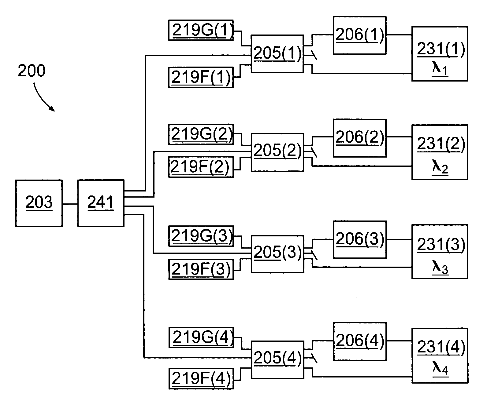
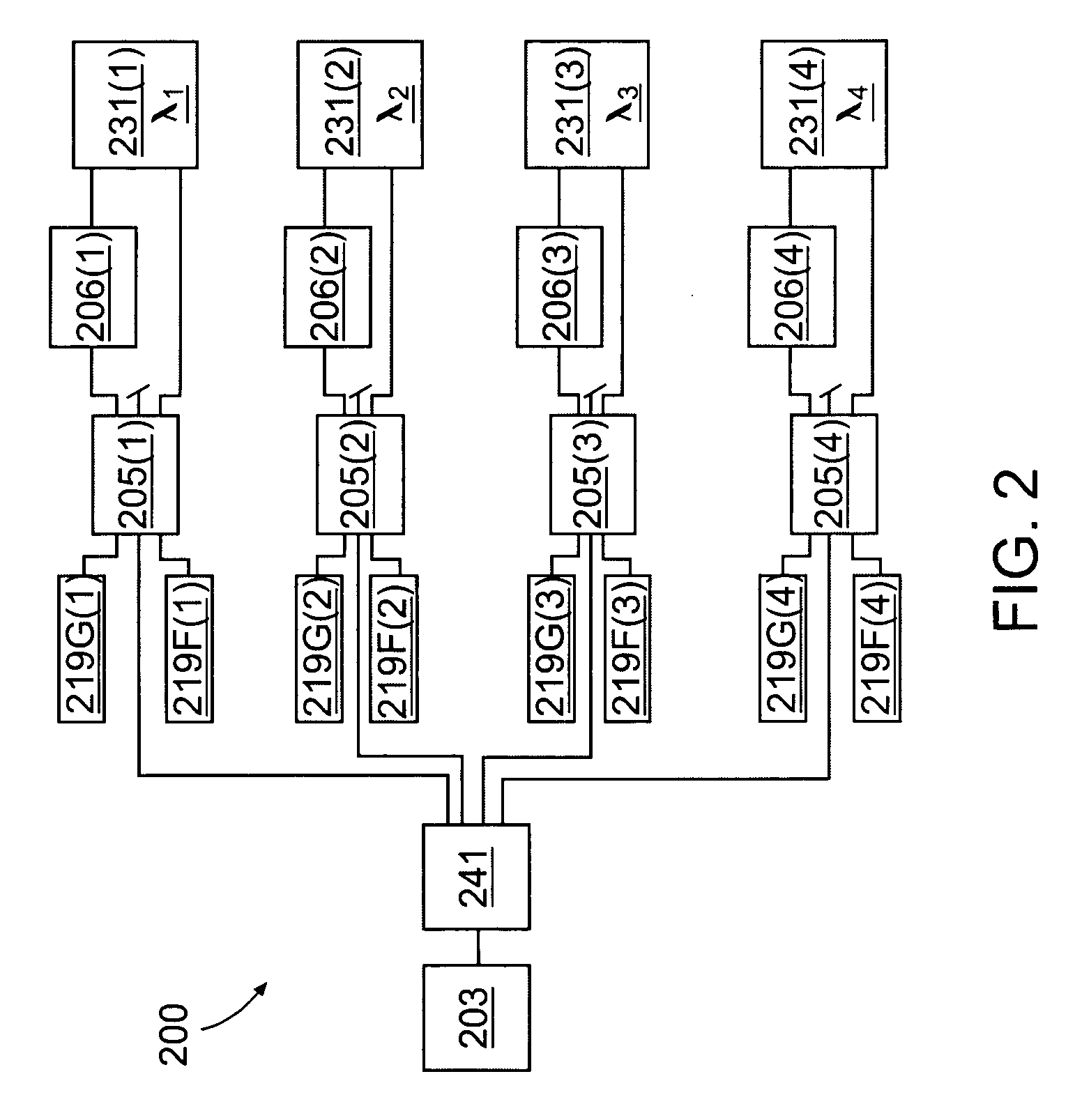
[0009] The present invention is directed to increasing the number of sensors that can be used by an SSA system comprising a single source by utilizing a multi wavelength source to send different wavelength pulses to each of a plurality of different sensor array ladders, particularly Sagnac sensor array (SSA) ladders. More particularly, each broadband pulse from a broadband source is wavelength divided into a plurality of narrower pulses with each narrower pulse being used in a separate sensor array ladder.

Problems solved by technology

As a result, the pulses for a particular rung interfere with each other.
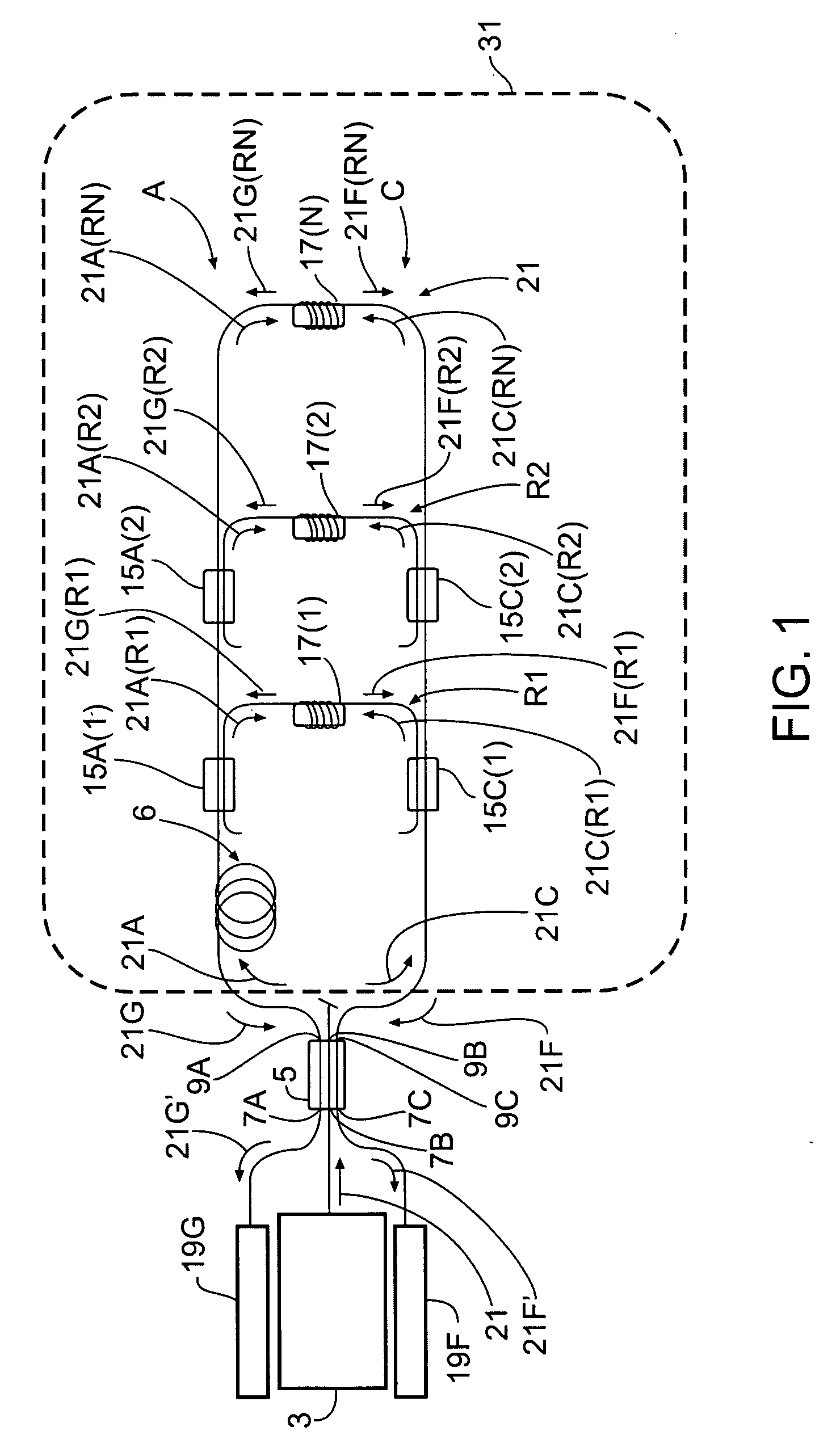
Unfortunately, having a limit on the number of sensors limits the amount of area the SSA system 1 can cover.
Having a limit on the number of sensors also limits the sensing capabilities of the SSA system 1.
However, “ladders” and “SSA ladders”, as the terms are used in the detailed description, do not necessarily include a delay coil.

Method used


Image

  • Multi wavelength sensor array
  • Multi wavelength sensor array
  • Multi wavelength sensor array

Examples


Embodiment Construction

[0019] Reference will now be made to the preferred embodiments of the invention, examples of which are illustrated in the accompanying drawings. While the invention will be described in conjunction with the preferred embodiments, it will be understood that these embodiments are not intended to limit the invention. On the contrary, the invention is intended to cover alternatives, modifications and equivalents, which may be included within the spirit and scope of the invention as defined by the appended claims.

[0020] In the following detailed description, numerous specific details are set forth in order to provide a thorough understanding of the present invention. However, it will be understood by one of ordinary skill in the art that the present invention may be practiced without these specific details. In other instances, well known methods, procedures, components, and circuits have not been described in detail so as not to unnecessarily obscure the important aspects of the present...


PUM


Abstract

The number of sensors that can be used by an SSA system including a single source can be increased by using a multi wavelength source to send different wavelength pulses to each of a plurality of different sensor array ladders, particularly Sagnac sensor array (SSA) ladders. More particularly, each broadband pulse from a broadband source is wavelength divided into a plurality of narrower pulses with each narrower pulse being used in a separate sensor array ladder.

Description

FIELD OF THE INVENTION [0001] The present invention relates generally to fiber optic sensor arrays. BACKGROUND OF THE INVENTION [0002]FIG. 1 depicts a prior art Sagnac sensor array (SSA) system 1 comprising a source 3, a coupler 5 having input ports 7A-7C and output ports 9A-9C, a clockwise distribution and agglomeration bus A, a counterclockwise distribution and agglomeration bus C, clockwise channel couplers 15A(1)-15A(N-1) where N-1=2, counter clockwise channel couplers 15C(1)-15C(N-1) where N-1=2, rungs R1-RN, sensors 17(1)-17(N), and detectors 19F and 19G. Reference to the 3rd rung as the N rung is intended to show that the actual number of rungs may vary between different sensor arrays. [0003] In the SSA system 1, a signal 21 comprising a series of pulses of light is generated by the intensity modulated source 3 coupled to the 3×3 optical coupler 5. The coupler 5 splits the signal 21 equally among the three output ports 9A, 9B, and 9C, such that each pulse of the signal 21 out...

Claims


Application Information

Patent Timeline
IPC IPC(8): G02B6/26
CPCG01D5/35383G01H9/00G01S3/80
Inventor MEYER, A. DOUGLAS
Owner LITTON SYST INC
Learn More