Total contact thoraco-lumbosacral spinal orthosis

a thoracic and lumbosacral technology, applied in the field of total contact thoracic lumbosacral spinal orthosis, can solve the problems of inability to transmit referred forces, complicated doff, and difficult for patients to tighten sufficiently

Inactive Publication Date: 2006-12-21
RAUCH ISABELLE
View PDF18 Cites 8 Cited by
  • Summary
  • Abstract
  • Description
  • Claims
  • Application Information

AI Technical Summary

Benefits of technology

[0014] It is an object of the present invention to overcome the drawbacks of the prior art. In this regard, it is an object of the present invention to provide an anterior attachment capable body jacket that also features the light-weight, ease of doffing and ease of adjustment features of an anterior opening or anterior overlap body jacket.
[0015] It is another object of the present invention to provide a spinal orthotic, including; a total contact module constructed of a single piece of a semi-rigid semi-resilient material, the total contact module having an anterior overlap, a longitudinal pressure bar positioned anterior to the total contact module, the longitudinal pressure bar spanning first and second posteriorly directed force vectors, a module attachment at the first posteriorly directed force vector, the module attachment attaching a module attachment end of the longitudinal pressure bar to the total contact module, a chest plate attachment at the second posteriorly directed force vector, the chest plate attachment attaching a chest plate attachment end of the longitudinal pressure bar to a chest plate, at least one adjustable strap on the module spanning the anterior overlap, at least one of the at least one adjustable strap being capable of increasing the anterior overlap to reduce a circumferential size of the total contact module thereby increasing abdominal hydraulic pressure, at least one of the at least one adjustable strap being capable of inducing an anteriorly directed third force parallel with, between, and diametrically opposite the first and second forces by connecting a tenth thoracic vertebrae proximal region on a posterior side of the total contact module with a posterior pressure directing anchor point on the longitudinal pressure bar between the chest plate attachment end and the module attachment end; and, the first, second, and third forces collectively forming a three point pressure system having a spinal extension directing effect.

Problems solved by technology

PA1 an orthosis of the old canvas construction is incapable of transmitting referred forces through attachments, complicated to doff, bulky, difficult for patients to tighten sufficiently to be effective, and cannot easily provide the rigidity of support needed.
Here each orthotic has such a structure but additional strapping is still requires and the addition of the support panels adds extra weight to the already bulky cloth devices.
The approach produces a light, minimally structured device but ignores the augmenting advantages of intra-abdominal hydraulic pressure stiffening.
This force-concentrating feature results in a brace that is often uncomfortable and sometimes painful.
Also, these devices having little surface contact have poor ability to provide reliable alignment stability features.
The problematic drawbacks, are the heaviness of the devices (often 6-15 lbs), and the difficulties in doffing and tightening all the many adjustment straps evenly to attain efficacious snugness and alignment.
However, if an anterior attachment is prescribed, the doffing / adjustment process is very difficult without the help of a second party.
Additionally, the longitudinal and tortional skew stability of the jacket at the anterior or posterior opening is dependant solely on the straps bridging the opening, creating an unstable location for an attachment and making lateral stability less efficacious.
It is considered useful for addition of a Knight Taylor extension but because of the anterior location of the overlap flaps this orthosis is not thought useful for the addition of anterior extensions.
Also it is disfavored for anterior attachments because of the perceived difficulty of maintaining medial alignment, in the face of frequent size adjustment necessary accommodate ongoing changes in the patient body size and shape, for an attachment that is located on a closure flap.

Method used


Image

  • Total contact thoraco-lumbosacral spinal orthosis
  • Total contact thoraco-lumbosacral spinal orthosis
  • Total contact thoraco-lumbosacral spinal orthosis

Examples


Embodiment Construction

)

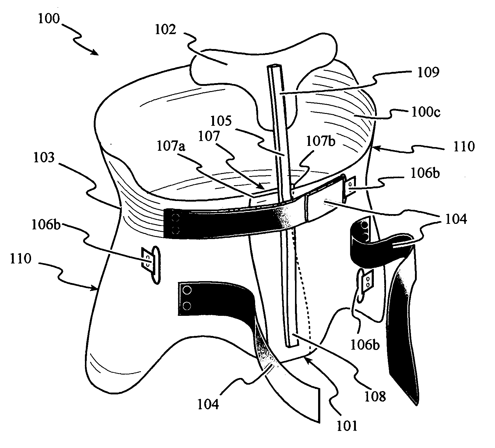
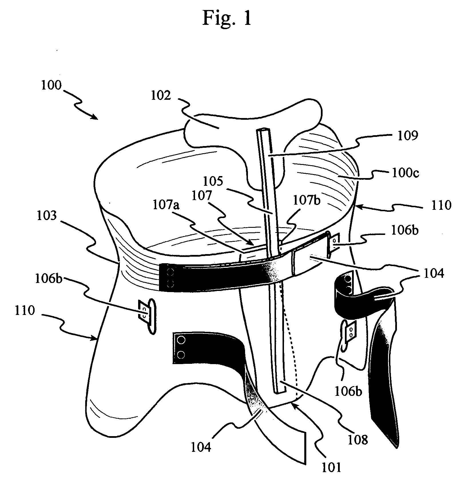
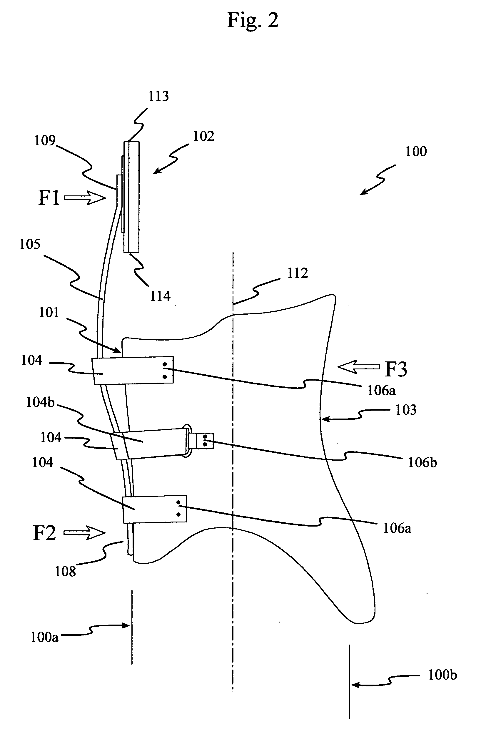
[0070] Referring to FIGS. 1 and 2, an embodiment of the present invention, a total contact module 100, having an anterior face 100a, a posterior face 100b, and lateral faces 100c, is connected to a chest plate 102. Total contact module 100, constructed of semi-rigid contourable plastic sheet laminate material of an outer plastic shell 100d layer with a resilient lining 100e layer, wraps around the patient and forms an overlap 107 at anterior face 100a. Overlap 107 allows total contact module 100 to be adjusted to varying levels of tightness by some type of adjustment mechanism. Shown here adjustment is accomplished by multiple opposite facing adjustment straps 104 attached to total contact module 100 on laterally opposite sides of overlap 107 at one side by a non-removable strap attachment 106a and at the opposite side by looping through a strap loop 106b and folding back onto itself Adjustment straps 104 alternate direction with first adjustment strap 104 having non-removable stra...


PUM


Abstract

The present invention is an anterior opening one piece total contact spinal orthotic device with an anterior attached upper body attachment that combines a three point pressure system for spinal hyperextension with an abdominal hydraulic pressure support system. This is accomplished by including a longitudinal pressure bar in the medial sagittal plane that attaches to the lower anterior face of an overlap style total contact module and at the upper end to a chest plate. The chest plate is either a sternal plate or a pectoral pad bridge unit. The medial posterior point proximal to T-10 or there about is anchored to the pressure bar through the upper structure of the total contact module. A variety of additional attachments, features and options are accommodated.

Description

FIELD OF THE INVENTION [0001] This invention relates to orthotic devices. More specifically, this invention relates to orthotic devices that provide rigid frame spinal bracing of upper body musculoskelatal injury or disease occurring in the thoracic, lumbar or sacral region to the sacral pelvic region. BACKGROUND [0002] The normal anatomy of the spine is usually described by dividing up the spine into 4 major sections: the cervical, the thoracic, the lumbar, and the sacral spines. Each section is made up of individual bones called vertebrae. There usually are 7 cervical vertebrae, 12 thoracic vertebrae, and 5 lumbar vertebrae. The sacrum, below the lumbar vertebrae, is the spinal part of the pelvis and is considered to be 5 vertebrae that have fused into one bone. [0003] An individual vertebra is made up of several parts. The body of the vertebra is the primary area of weight bearing and provides a resting place for the fibrous discs which separate each of the vertebrae. The lamina ...

Claims


Application Information

Patent Timeline
Patent Type & Authority Applications(United States)
IPC IPC(8): A61F5/00
CPCA61F5/024
Inventor RAUCH, ISABELLE
Owner RAUCH ISABELLE
Why Eureka
Try Eureka