Artificial cornea

a corneal implant and artificial technology, applied in the field of artificial corneal implants, can solve the problems of future shortage of corneas, loss of vision, and blindness, and achieve the effect of enabling long-term optical clarity and maintaining passivity to protein adsorption

Inactive Publication Date: 2006-12-21
THE BOARD OF TRUSTEES OF THE LELAND STANFORD JUNIOR UNIV
View PDF22 Cites 32 Cited by
  • Summary
  • Abstract
  • Description
  • Claims
  • Application Information

AI Technical Summary

Benefits of technology

[0008] In a preferred embodiment, biomolecules are linked to the skirt, central core or both. These biomolecules may be any type of biomolecule, but are preferably biomolecules that support epithelial and / or fibroblast cell survival and growth. Examples of such biomolecules include, but are not limited to, collagen, fibronectin, laminin, amino acids, carbohydrates, lipids and nucleic acids. Preferably, the biomolecules are linked in a spatially selective manner. For example, the bulk and posterior of the implant's central core may remain unmodified by molecules to maintain passivity to protein adsorption and to enable long-term optical clarity.

Problems solved by technology

Most of these will remain blind due to limitations of human corneal transplantation.
The major barriers for treating these patients are corneal tissue availability and resources, particularly for people in developing countries.
Therefore, a shortage of corneas may occur in the future, even in developed countries, as the number of patients undergoing refractive surgery increases.
Even among patients who are fortunate enough to receive a corneal transplant, a significant number will develop complications that will result in the loss of vision.
The most common complications are graft rejection and failure and irregular or severe astigmatism.
In successful cases, the improvement in vision may take many months following the surgery due to graft edema and astigmatism.

Method used


Image

  • Artificial cornea
  • Artificial cornea
  • Artificial cornea

Examples


examples

Photolithographically Patterned Artificial Cornea

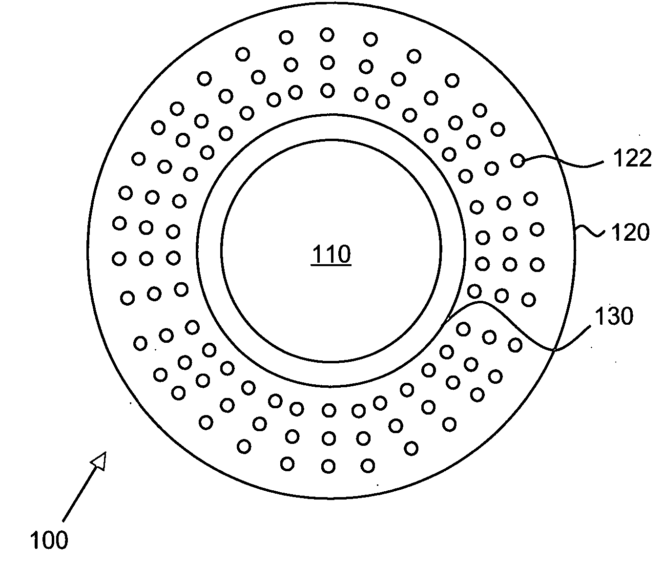
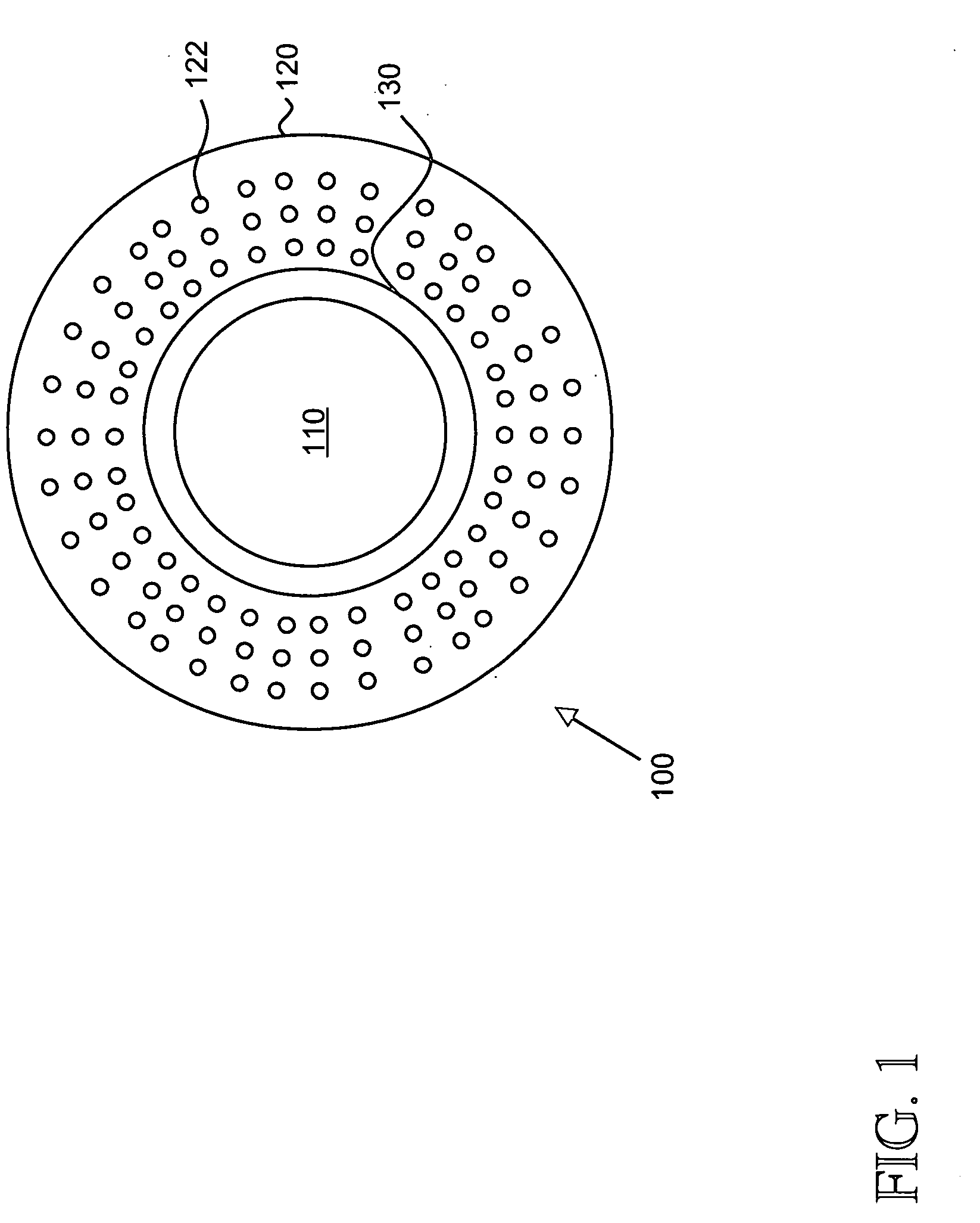
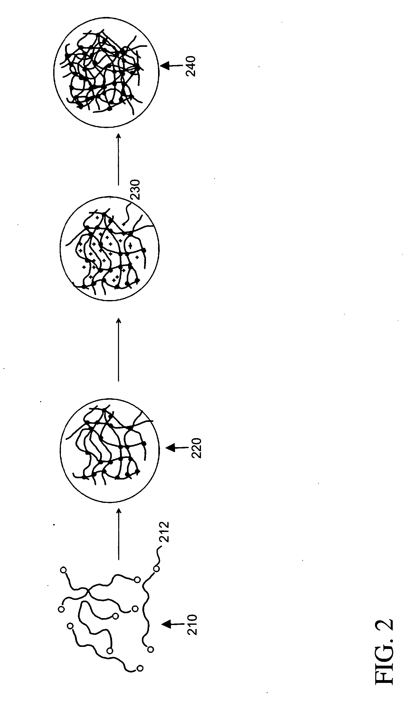
[0059]FIG. 9 shows a photomicrograph of a photolithographically patterned artificial cornea 910 with optically clear central core 920 and porous peripheral skirt 930. In this example, the central core was made of a PEG / PAA double network and the skirt was made of PHEA. The PEG / PAA hydrogel was synthesized by a two-step sequential network formation technique based on UV initiated free radical polymerization. A precursor of the first solution was made of purified PEG-diacrylate (MW 8000) dissolved in deionized water with hydroxymethyl propiophenone as the UV sensitive free radical initiator. The solution was cast into a Teflon mold, covered with a glass plate, and reacted under a UV light source at room temperature. Upon exposure, the precursor solution underwent a free-radical induced gelation and became insoluble in water. To incorporate the second network, the PEG hydrogel was removed from the mold and immersed in a 50% v / v acrylic...


PUM


Abstract

The present invention provides an artificial corneal implant having an optically clear central core and a porous, hydrophilic, biocompatible skirt peripheral to the central core. In one embodiment, the central core is made of an interpenetrating double network hydrogel and the skirt is made of poly(2-hydroxyethyl acrylate) (PHEA). In another embodiment, both the central core and the skirt are made of interpenetrating double network hydrogels. The artificial corneal implant may also have an interdiffusion zone in which the skirt component is interpenetrated with the core component, or vice versa. In a preferred embodiment, biomolecules are linked to the skirt, central core or both. These biomolecules may be any type of biomolecule, but are preferably biomolecules that support epithelial and/or fibroblast cell survival and growth. Preferably, the biomolecules are linked in a spatially selective manner. The present invention also provides a method of making an artificial corneal implant using photolithography.

Description

CROSS-REFERENCE TO RELATED APPLICATIONS [0001] This application claims priority from U.S. Provisional Patent Application No. 60 / 673,600, filed Apr. 21, 2005, which is incorporated herein by reference. This application is a continuation-in-part of U.S. patent application Ser. No. 11 / 243,952, filed Oct. 4, 2005, which claims priority from U.S. Provisional Patent Application No. 60 / 616,262, filed Oct. 5, 2004, and from U.S. Provisional Patent Application No. 60 / 673,172, filed Apr. 20, 2005, all of which are incorporated by reference herein. FIELD OF THE INVENTION [0002] The present invention relates generally to corneal implants. More particularly, the present invention relates to artificial corneal implants based on an interpenetrating double network hydrogel core and a peripheral hydrogel skirt. BACKGROUND [0003] It is estimated that there are 10 million people worldwide who are blind due to corneal diseases (See e.g. Carlsson et al. (2003) in a paper entitled “Bioengineered corneas:...

Claims


Application Information

Patent Timeline
Patent Type & Authority Applications(United States)
IPC IPC(8): A61F2/14A61K35/12
CPCA61F2/14A61K35/12A61F2/142A61F2/15
Inventor MYUNG, DAVIDTA, CHRISTOPHERFAROOQUI, NABEELFRANK, CURTIS W.KOH, WON-GUNKO, JUNGMINNOOLANDI, JAANCARRASCO, MICHAEL R.
Owner THE BOARD OF TRUSTEES OF THE LELAND STANFORD JUNIOR UNIV
Why Eureka
Try Eureka