Mechanical apparatus and method for artificial disc replacement

a mechanical apparatus and artificial disc technology, applied in the field of artificial disc replacement devices and methods, can solve the problems of increasing the compressive load of the annulus, increasing the risk of delamination and damage of the annulus, and affecting so as to increase the overall diameter of the loop

Inactive Publication Date: 2006-12-21
OUROBOROS MEDICAL INC
View PDF7 Cites 130 Cited by
  • Summary
  • Abstract
  • Description
  • Claims
  • Application Information

AI Technical Summary

Benefits of technology

[0012] The expansile loop may be formed such that when the loop is diametrically contracted one end of the loop feeds into its other end, similar to a snake eating its own tail. Alternatively, the expansile loop may be formed such that when it is diametrically...

Problems solved by technology

Inter-vertebral disc disease is a major worldwide health problem.
Loss of water binding by the nucleus results in more compressive loading of the annulus.
This renders the annulus more susceptible to delamination and damage.
Damage to the annulus, in turn, accelerates disc degeneration and degeneration of surrounding tissues such as the facet joints.
These procedures only address the symptom of lower back pain.
Both procedures actually worsen the overall condition of the affected disc and the adjacent discs.
However device failure has been reported along with dislocation and migr...

Method used


Image

  • Mechanical apparatus and method for artificial disc replacement
  • Mechanical apparatus and method for artificial disc replacement
  • Mechanical apparatus and method for artificial disc replacement

Examples


Embodiment Construction

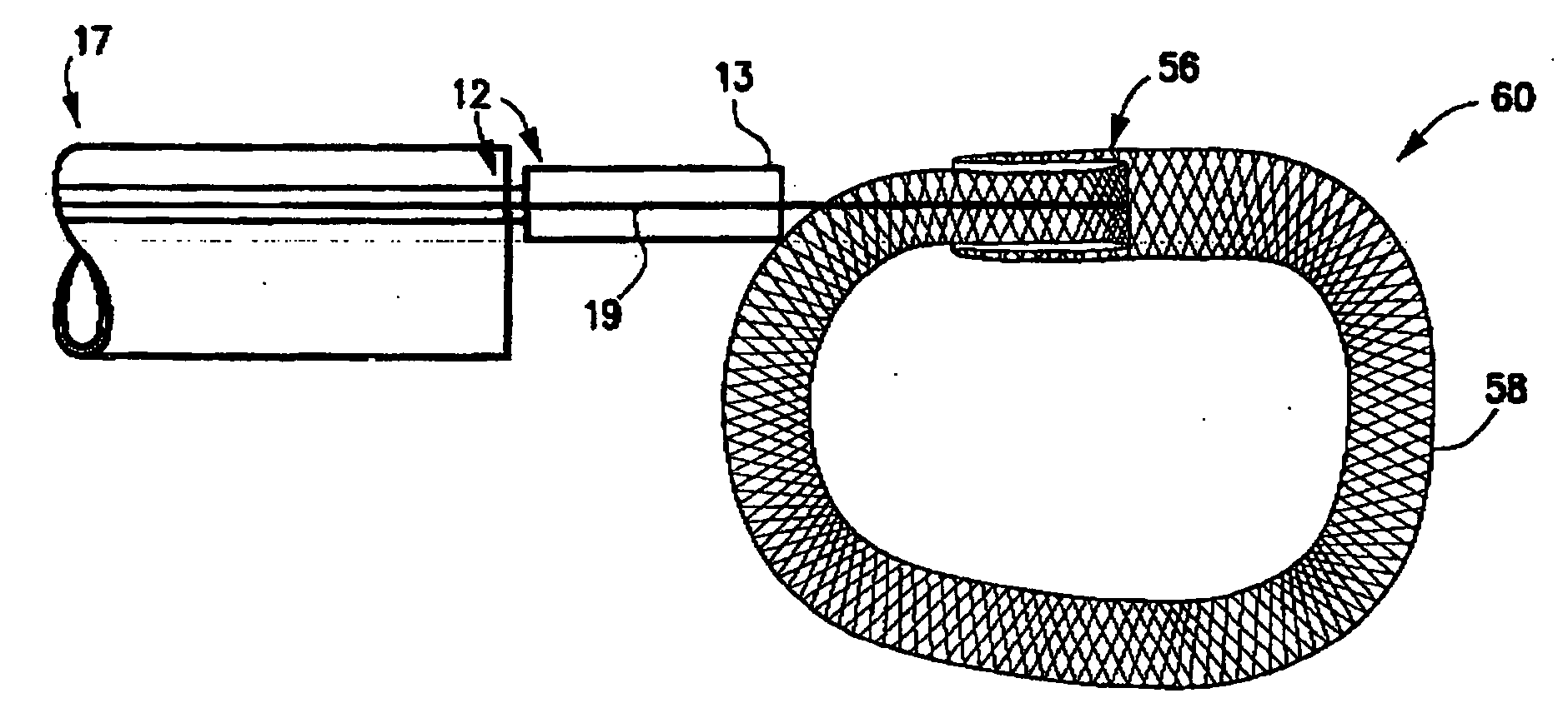
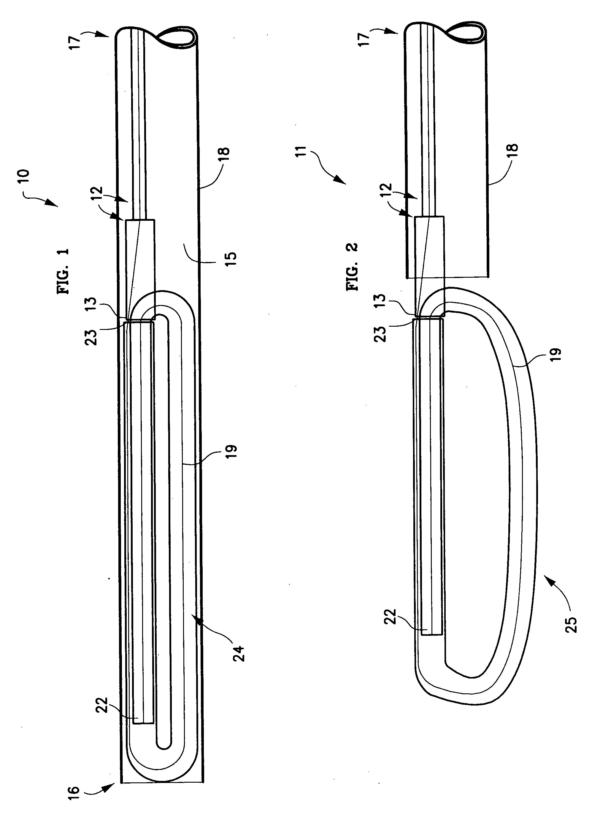
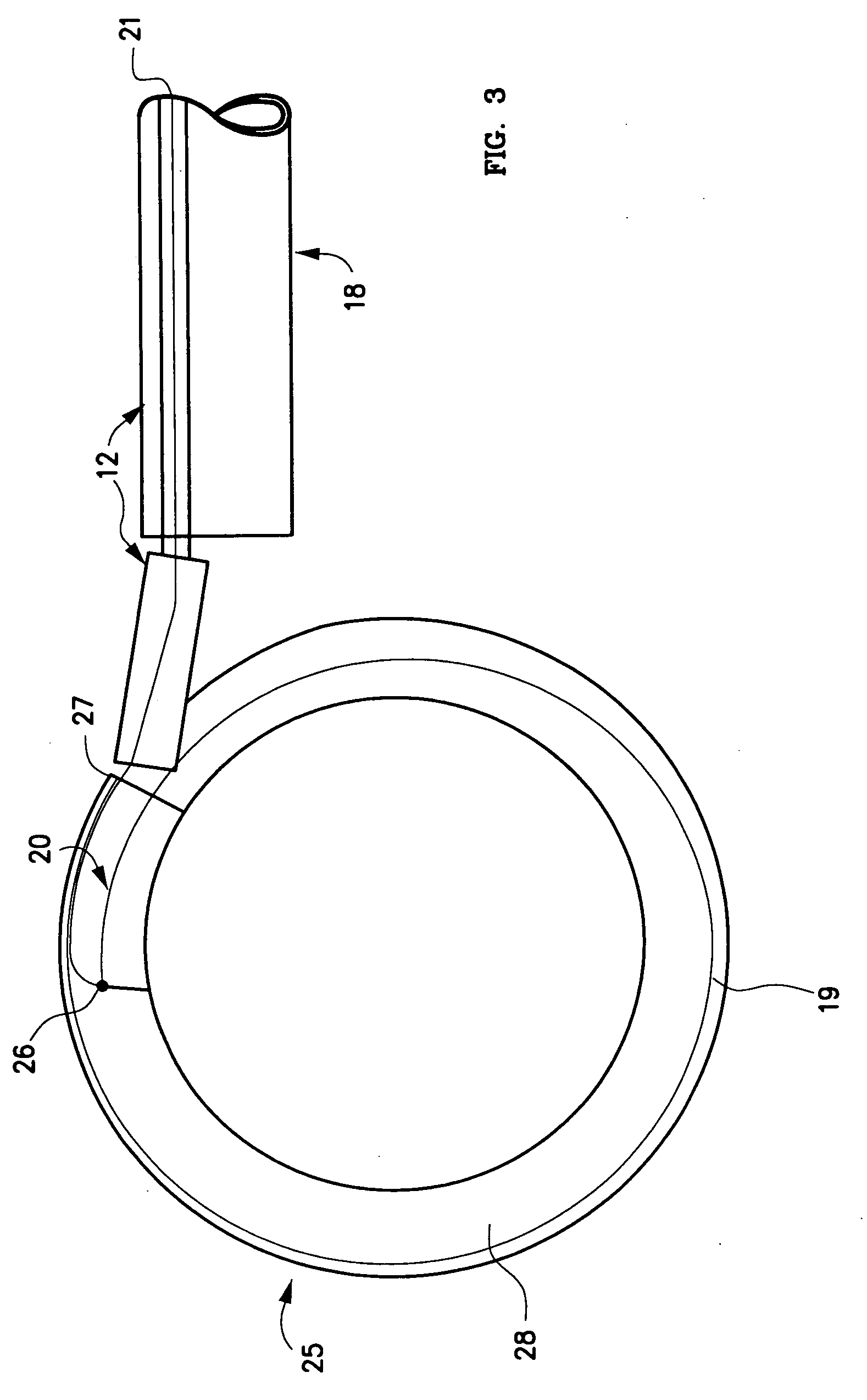
[0043] One embodiment 10, 11 of the spinal disc device, as shown in FIGS. 1-5, consists of an elongated probe 15, with a proximal end 17 and a distal end 16. Referring to FIGS. 1 and 2, is can be seen that the elongated probe 15 is constructed from at least two elements, a flexible inner catheter control element 19, and a stiffer outer catheter element 12. The inner catheter control element 19 is slideably located within the outer catheter element 12. At the proximal end 17 of elongated probe 15, the inner catheter control element 19 exits from the outer catheter element 12, and can be advanced or retracted causing the distal end 20 of the inner catheter control element 19 to move in or out of the distal end 13 of the outer catheter element 12. Near the distal end 16 of the elongated probe 15, is situated an expansile, braided or woven tubular loop 24 in a contracted or delivery configuration (FIG. 1). The inner catheter control element 19 enters the expansile loop 24 near the dista...


PUM

PropertyMeasurementUnit
Diameteraaaaaaaaaa
Flexibilityaaaaaaaaaa
Biocompatibilityaaaaaaaaaa

Abstract

The present invention relates to a device and method which may be used to reinforce the native annulus during spinal surgery. The device is a catheter based device which is placed into the inter-vertebral space following discectomy performed by either traditional surgical or endoscopic approaches. The distal end of the catheter is comprised of an expansile loop which may be increased in diameter by advancement of a portion of the catheter via its proximal end, such proximal end remaining external to the body. The expansile loop may be formed of a woven or braided material and may be made of a polymer such as nylon, polyurethane, polyester, polyethylene, polypropylene or any of the well known and biocompatible polymers. Alternatively the expansile portion of the catheter may be formed from a metallic braid of stainless steel, elgiloy, Nitinol, or other biocompatible metals. The expansile loop may be formed such that when the loop is diametrically contracted the loop feeds into its other end, similar to a snake eating its own tail. Stabilization of the outer portion of the loop and pulling out the inner portion will thereby increase the overall diameter of the loop while maintaining it as a closed loop or torus. The present invention comprises four embodiments and can be used to 1) facilitate disk fusing, 2) perform an artificial replacement of the nucleus, 3) perform an artificial replacement of the annulus, or 4, perform an artificial replacement of both the nucleus and annulus.

Description

CROSS-REFERENCES [0001] The present application is a continuation-in-part of patent application Ser. No. 11 / 153,776 filed on Jun. 15, 2005. This application is incorporated herein by this reference.FIELD OF THE INVENTION [0002] The present invention generally relates to devices and methods for the repair of inter-vertebral discs. More, specifically, the present invention relates to devices and methods for the treatment of spinal disorders associated with the nucleus, annulus and inter-vertebral disc. BACKGROUND OF THE INVENTION [0003] Inter-vertebral disc disease is a major worldwide health problem. In the United States alone almost 700,000 spine procedures are performed each year and the total cost of treatment of back pain exceeds $30 billion. Age related changes in the disc include diminished water content in the nucleus and increased collagen content by the 4th decade of life. Loss of water binding by the nucleus results in more compressive loading of the annulus. This renders t...

Claims


Application Information

Patent Timeline
IPC IPC(8): A61F2/44
CPCA61B17/04A61F2310/00365A61B17/842A61B17/86A61B17/869A61F2/28A61F2/441A61F2/4455A61F2/4611A61F2002/2835A61F2002/30062A61F2002/30075A61F2002/30092A61F2002/302A61F2002/30235A61F2002/30462A61F2002/3052A61F2002/30579A61F2002/30583A61F2002/30601A61F2002/4435A61F2002/444A61F2002/4495A61F2002/4627A61F2002/4629A61F2210/0004A61F2210/0014A61F2210/0061A61F2210/0085A61F2220/0025A61F2220/0075A61F2230/0065A61F2230/0069A61F2310/00011A61F2310/00353A61B17/064A61F2/44
Inventor SEGAL, JEROMEYUREK, MATTHEW THOMAS
Owner OUROBOROS MEDICAL INC
Why Eureka
Try Eureka