
Crimp contact and gas sensor

a technology of crimp contact and gas sensor, which is applied in the direction of instruments, chemical methods analysis, material analysis, etc., can solve the problems of gas sensor with such a conventional crimp contact not being able to secure accurate signal output, and not being able to hold lead core wires sufficiently tightly, so as to prevent or minimize a widening of clearance, avoid an increase in electrical resistance, and secure accurate signal output over a long period of time

Inactive Publication Date: 2006-12-28
NGK SPARK PLUG CO LTD
View PDF5 Cites 3 Cited by
  • Summary
  • Abstract
  • Description
  • Claims
  • Application Information

AI Technical Summary

Benefits of technology

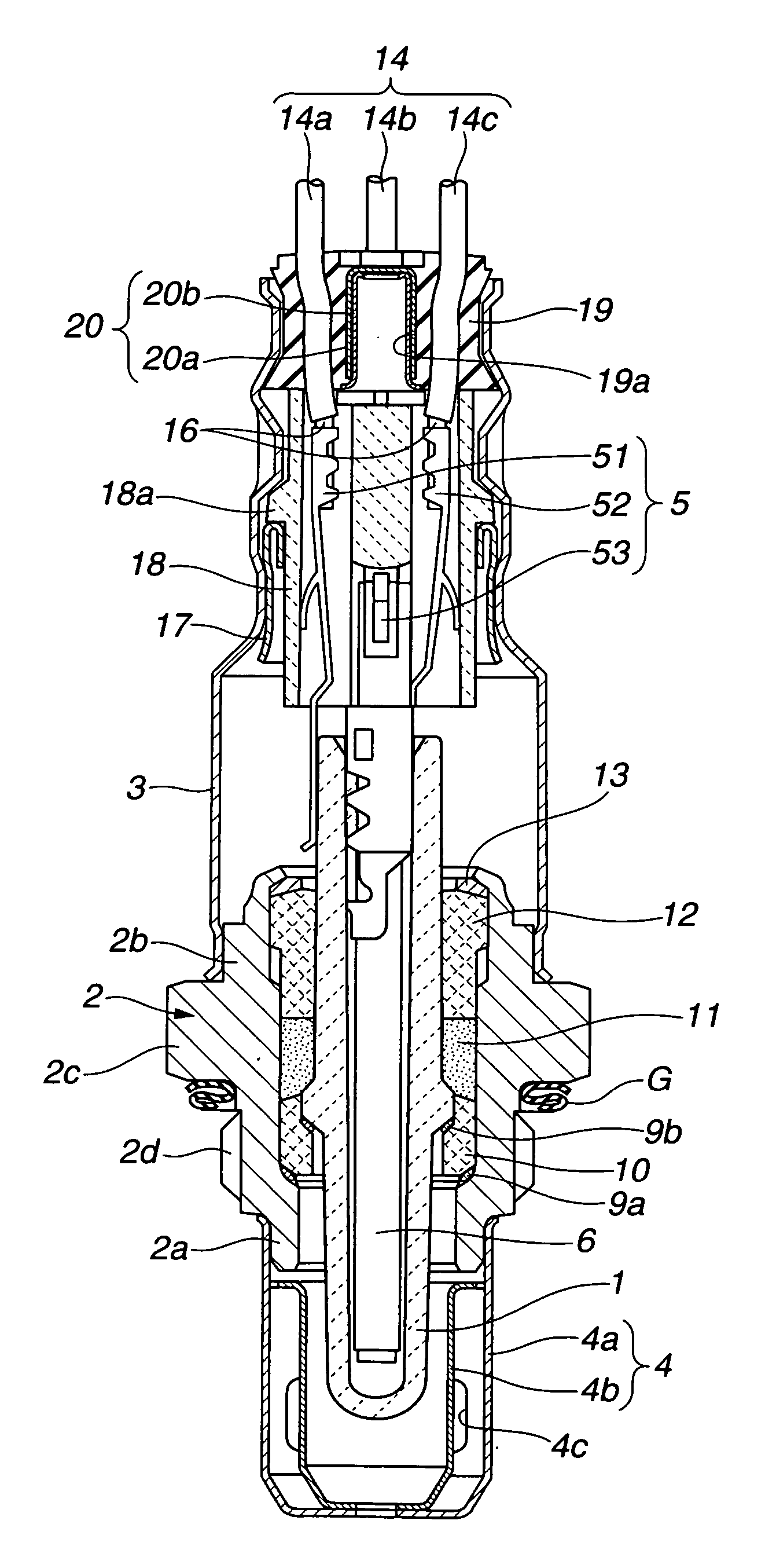
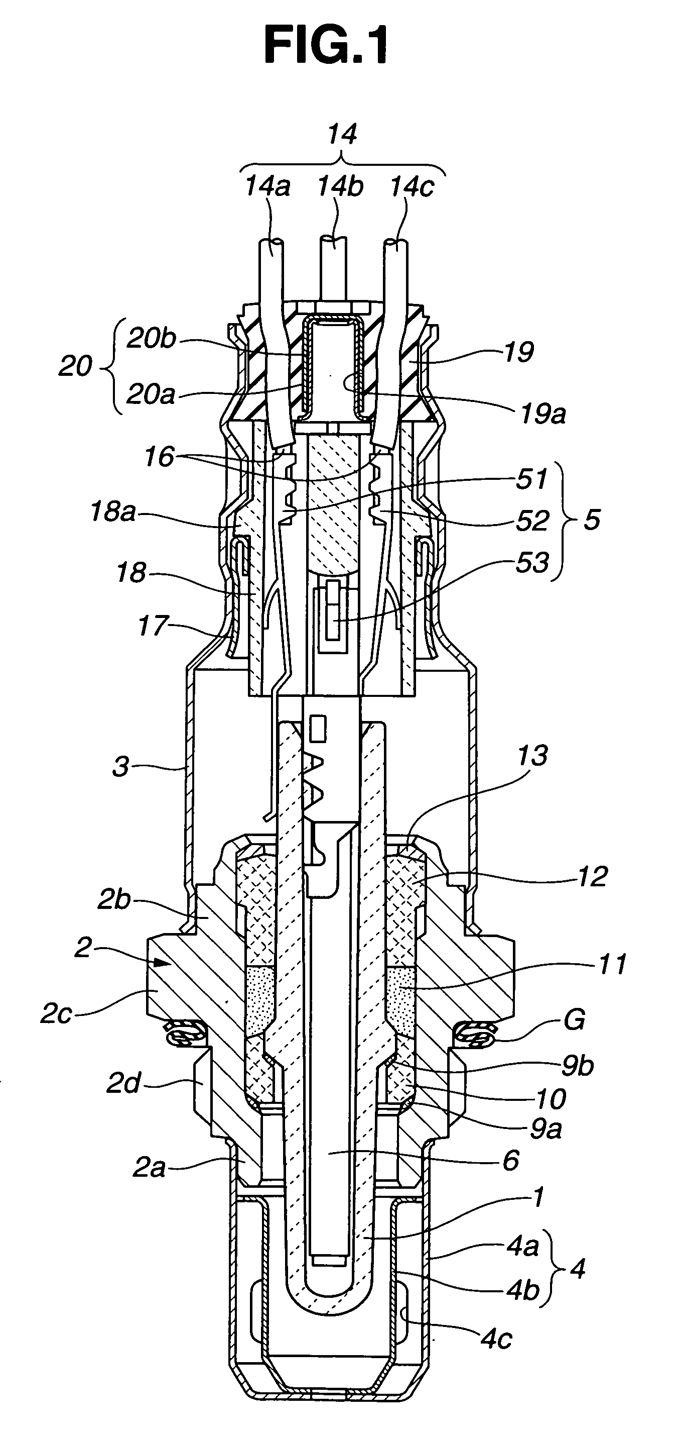
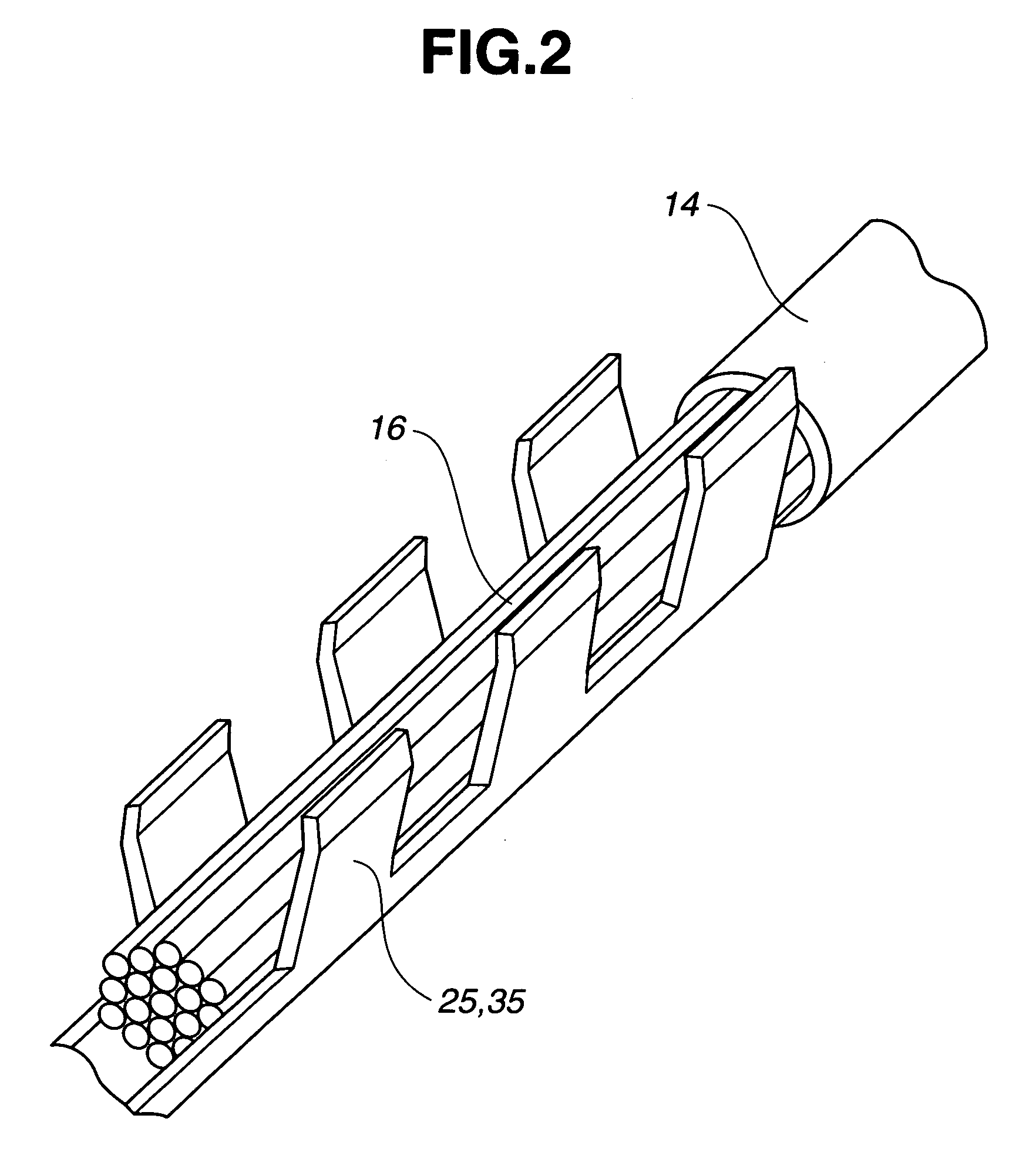
[0003] In order for the gas sensor to secure accurate signal output over a long period of time, it is desirable that the wire hold portions of the crimp contact hold the lead core wires tightly so as to prevent or minimize a widening of clearance between the wire hold portions and the lead core wires and avoid an increase in electrical resistance between the crimp contact and the electrical lead during the heating and cooling cycles of operation of the gas sensor.
[0005] It is therefore an object of the present invention to provide a crimp contact capable of holding an electrical lead wire tightly and securely, regardless of the crimping process conditions (the use or disuse of a lubricant in the crimping process) and the crimp contact material, without causing an increase in electrical resistance between the crimp contact and the lead wire even when subjected to loads of the heating / cooling cycle operation.
[0006] It is also an object of the present invention to provide a gas sensor having such a crimp contact to secure accurate signal output over a long period of time.

Problems solved by technology

In the above-mentioned conventional crimp contact, however, the wire hold portions are simply crimped onto the lead core wires with no specific dimension control through the application of a lubricant and thus may not be able to hold the lead core wires sufficiently tightly.
It is further difficult in the conventional crimp contact to bend the wire hold portions adequately during the crimping process depending on the crimping process conditions (where the use of the lubricant is impractical in view of the crimp contact quality) and the crimp contact material so that the wire hold portions cannot hold the lead core wires tightly.
The gas sensor with such a conventional crimp contact fails to secure accurate signal output over a long period of time.

Method used


Image

  • Crimp contact and gas sensor
  • Crimp contact and gas sensor
  • Crimp contact and gas sensor

Examples


example 1

[0050] Test samples of crimp contacts 5 of the first embodiment were prepared, each of which had three wire hold portions 5a crimped onto nineteen lead core wires 16 as shown in FIG. 5. The wire hold portions 5a were herein made of Inconel. The lead core wires 16 were made of pure copper and had a diameter of 0.2 mm before the crimping process. The crimping process was performed using an anvil 22 and a crimper 24 as shown in FIG. 4 without the application of a lubricant. Each of the completed wire hold portions 5a had a bottom wall 5b and side walls 5c, with top ends 5d of the respective side walls 5c turned toward the bottom wall 5b and outer surfaces 5e of the respective side wall ends 5d brought in contact with each other, to enclose the lead core wires 16 in a wire accommodation space 5f as shown in FIG. 6.

[0051] For cross section observation of the wire hold portion 5a, one of the test samples of the crimp contacts 5 was cut at a joint between the wire hold portion 5a and the ...

example 2

[0055] Test samples of crimp contacts 5 of the second embodiment were prepared, each of which had three wire hold portions 5a crimped onto nineteen lead core wires 16 as shown in FIG. 5. The wire hold portions 5a were made of Inconel. The lead core wires 16 were made of pure copper and had a diameter of 0.2 mm before the crimping process. The crimping process was performed using an anvil 22 and a crimper 24 as shown in FIG. 4 without the application of a lubricant. Each of the completed wire hold portions 5a had a bottom wall 5b and side walls 5c, with top ends 50c and 51c of the respective side walls 5c turned toward the bottom wall 5b and an end face 51g of the side wall end 51c brought in contact with an outer surface 50e of the side wall end 50c, to enclose the lead core wires 16 in a wire accommodation space 5f as shown in FIG. 7.

[0056] One of the test samples of the crimp contacts 5 was cut at a joint between the wire hold portion 5a and the lead core wires 16 along a directi...


PUM


Abstract

A crimp contact includes a wire hold portion crimped onto and holding therein core wires of an electrical lead. The wire hold portion has a bottom wall and a pair of side walls bent in such a manner as to bring ends of the side walls into contact with each other to define a wire accommodation space and satisfies the following equations: {(W1−W2) / 2} / W3≦1.2 and H2 / H1>0.5 where W1 is a maximum width of the wire hold portion; W2 is a maximum width of the wire accommodation space; W3 is a minimum thickness of the bottom wall; H1 is a maximum thickness of the wire hold portion; and H2 is a maximum distance from an outermost point of the side wall to a tip point of the side wall end along a thickness direction of the wire hold portion.

Description

BACKGROUND OF THE INVENTION [0001] The present invention relates to a crimp contact and a gas sensor. Hereinafter, the term “front” refers to a sensing end side with respect to an axial direction of the gas sensor, and the term “rear” refers to a side opposite to the front side. [0002] Japanese Laid-Open Patent Publication No. 64-041184 discloses one conventional type of crimp contact that has wire hold portions extending axially and holding therein core wires of an electrical lead. The crimp contact is suitably used for e.g. a gas sensor in an automotive exhaust system to connect the electrical lead wire with a sensor element of the gas sensor for signal output from the sensor element to an external device. SUMMARY OF THE INVENTION [0003] In order for the gas sensor to secure accurate signal output over a long period of time, it is desirable that the wire hold portions of the crimp contact hold the lead core wires tightly so as to prevent or minimize a widening of clearance between...

Claims


Application Information

Patent Timeline
IPC IPC(8): G01N35/00
CPCH01R43/058H01R4/184
Inventor NISHIO, HISAHARUMATSUBARA, YOSHIAKIISHIDA, NOBORUMURASE, MASAAKIASAI, MASAHIROHISHIKI, MAKOTO
Owner NGK SPARK PLUG CO LTD
Learn More