Driving device for a hybrid vehicle, and a hybrid vehicle having the same

a hybrid vehicle and driving device technology, applied in the direction of machines/engines, electric control, engine starters, etc., can solve the problems of affecting the operation of the engine, the in-cylinder pressure cannot be fully reduced through the entire compression stroke of the engine, and the sudden decrease of the driving wheel propulsion force which propels the driving wheel, etc., to achieve the effect of lessening the increase and the decrease of the propulsion force and facilitating the operation of the vehicl

Inactive Publication Date: 2006-12-28
YAMAHA MOTOR CO LTD
View PDF7 Cites 37 Cited by
  • Summary
  • Abstract
  • Description
  • Claims
  • Application Information

AI Technical Summary

Benefits of technology

[0022] In accordance with one aspect of the present invention, a driving device for a hybrid vehicle is provided. The driving device preferably is mountable on a motorcycle or like vehicle that can lessen an increase and decrease in propulsion force not intended by an operator, even when a rotary electric machine for running the vehicle is outputting constant torque, thereby allowing the operator to easily operate the vehicle and to provide a hybrid vehicle.

Problems solved by technology

Thus, in the hybrid vehicles using the power distribution device, a sudden decrease in the driving wheel propulsion force which propels the driving wheel impacts the vehicle operation, even when the motor is outputting constant torque.
However, the in-cylinder pressure cannot be fully reduced through the entire compression stroke of the engine because of limitations on the phase range within which valve timing can be varied, even with the use of the variable valve timing mechanism.
The remaining in-cylinder pressure impacts engine operation in the form of a pumping loss when starting-up the engine.
That is, in the case where the hybrid drive unit using the power transmission device disclosed in JP 2003-191761 is mounted on a motorcycle, impact at engine start-up is an unintentional increase and decrease in propulsion force that needs to be decreased.
However, a motorcycle has a limited mounting space compared to an automobile and thus cannot acommodate a battery which becomes larger as its charging capacity increases or a larger motor for producing increased torque.

Method used


Image

  • Driving device for a hybrid vehicle, and a hybrid vehicle having the same
  • Driving device for a hybrid vehicle, and a hybrid vehicle having the same
  • Driving device for a hybrid vehicle, and a hybrid vehicle having the same

Examples


Embodiment Construction

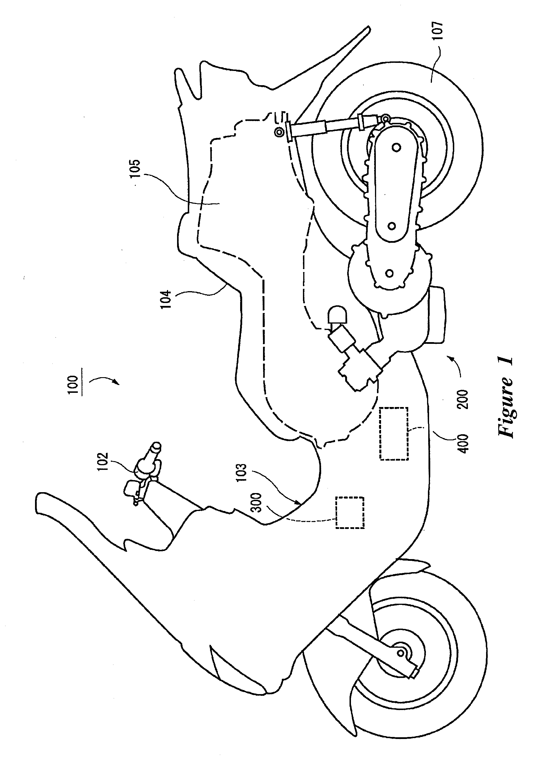
[0038]FIG. 1 is a schematic left side view of a scooter-type motorcycle 100 as an example of a hybrid vehicle incorporating a driving device for a hybrid vehicle according to an embodiment of the present invention. While the driving device is illustrated in connection with a scooter-type motorcycle, the driving device can be used with other types of vehicles as well.

[0039] The hybrid vehicle shown in FIG. 1 is a series-parallel hybrid scooter-type motorcycle in which a wheel is driven using an internal combustion engine and / or an electric motor as power sources. Specifically, in the hybrid vehicle (hereinafter referred to as “scooter-type motorcycle”), the engine power is split by a power split mechanism into two parts with a variable split ratio, of which one part is used to drive the wheel directly and the other part is used to generate electricity. In this embodiment, “front,”“rear,”“left,”“right,”“upper” and “lower” refer to the front, rear, left, right, upper and lower directi...


PUM


Abstract

An engine produces power, which is distributed by a power distribution device to an electric generator and a rear wheel. A motor produces power other than that produced by the engine to drive the rear wheel, and also functions as an electric generator. A control unit drives the electric generator and the motor using electricity from a battery to start up the engine. When starting up the engine, the control unit drives a decompression device provided in the engine to reduce the compression pressure inside a cylinder from the moment when cranking of the engine is started.

Description

CROSS-REFERENCE TO RELATED APPLICATIONS [0001] The present application is based on and claims priority under 35 U.S.C. 119 to Japanese Patent Application No. 2005-184141, filed on Jun. 23, 2005, the entire contents of which are incorporated by reference and should be considered part of this specification. BACKGROUND OF THE INVENTION [0002] 1. Field of the Invention [0003] The present invention relates to a driving device for a hybrid vehicle that incorporates a plurality of driving sources to run, and to a hybrid vehicle having the same. [0004] 2. Description of the Related Art [0005] There is an interest, from an environmental point of view, to reduce the discharge of pollutants from engine-driven vehicles as much as possible. In consideration of this, hybrid vehicles have been developed which utilize an electric motor (e.g., a rotary electric machine) in addition to an internal combustion engine to drive a driving wheel or driving wheels of the vehicle using the electric motor. [0...

Claims


Application Information

Patent Timeline
Patent Type & Authority Applications(United States)
IPC IPC(8): B60K1/00B60K6/20B60K6/44B60K6/445B60L50/16B60W10/06B60W10/08B60W20/00B62M23/02F02D15/00F02D29/02F02D45/00F02N11/04F02N11/08F02N99/00
CPCF01L13/08F02B61/02F02N19/004F02D29/02F02D2013/0292F02D13/0242
Inventor KATSUHIRO, ARAISAITOU, TETSUSHI
Owner YAMAHA MOTOR CO LTD
Why Eureka
Try Eureka