

Specimen holder for electron microscope
a technology of electron microscope and specimen holder, which is applied in the direction of instruments, heat measurement, machines/engines, etc., can solve the problems of inability to measure the site, the shape and function of the specimen holder is restricted, and it is impossible to make measurements at the microscopic measurement site selected on the specimen to achieve the effect of improving the manipulability
- Summary
- Abstract
- Description
- Claims
- Application Information
AI Technical Summary
Benefits of technology
Problems solved by technology
Method used
Image

Examples
embodiment 1
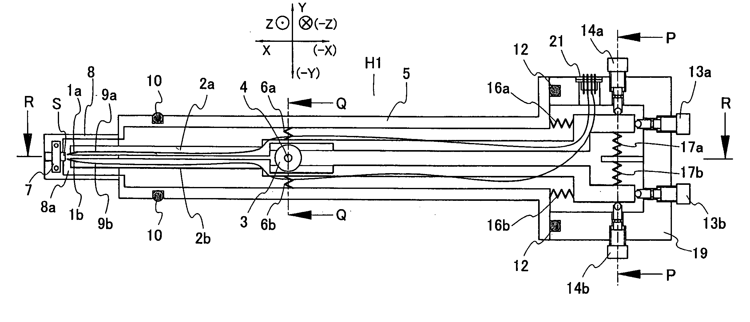
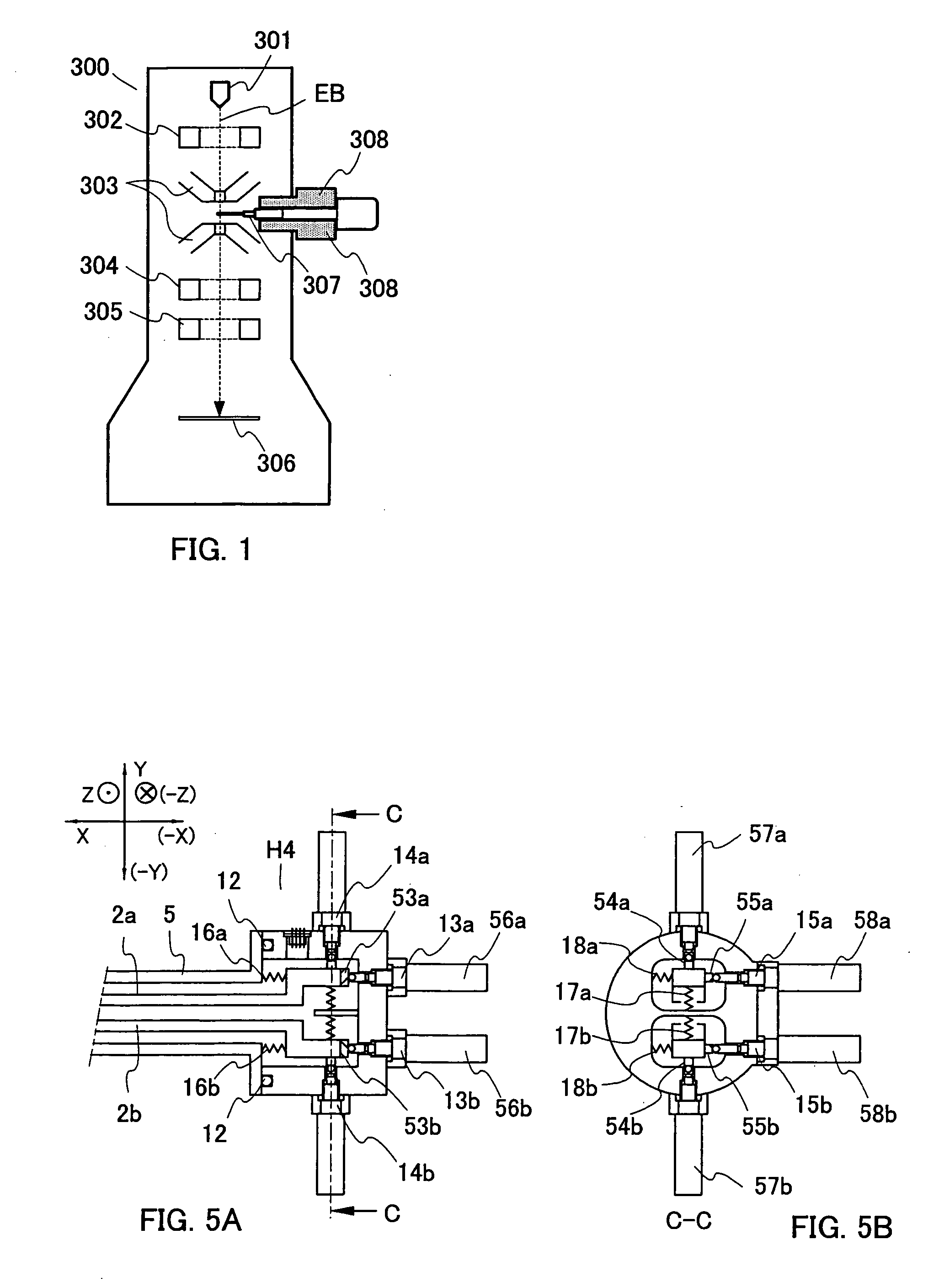
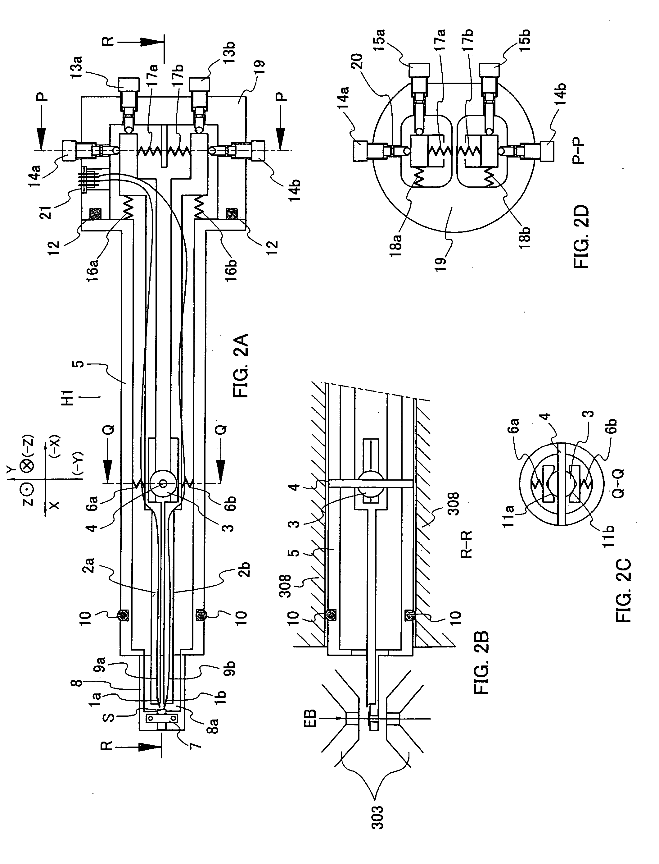
[0041]FIGS. 2A-2D show a specimen holder according to an embodiment of the present invention. FIG. 2A is a plan view of the specimen holder H1 as viewed from the side of the electron gun 301. FIG. 2B is a fragmentary cross section taken on line R-R of FIG. 2A. FIGS. 2C and 2D are cross-sectional views taken on lines Q-Q and P-P, respectively, of FIG. 2A. FIGS. 6A, 6B, and 6C show the front-end portion of the specimen holder H1 in enlarged form. FIG. 6A is a plan view of the front-end portion as viewed from the electron gun side. FIGS. 6B and 6C are cross-sectional views taken on lines D-D and E-E, respectively, of FIG. 6A. As shown in FIG. 6B, a specimen S is inserted in the narrow gap between the top and bottom polepieces 303 of the objective lens and tilted. For this purpose, the front end of the specimen holder H1 is made quite thin. To facilitate understanding the structure, the vertical dimension of the holder is shown to be exaggerated about twice compared with the actual dime...
embodiment 2
[0050] Another example of the structure of the pivotal point for moving the probes 1a and 1b in three dimensions is next described by referring to FIGS. 3A-3B. FIG. 3A is a plan view of the specimen holder H2 as viewed from a side of the electron gun 301. The right half (on the negative side of the X-axis) of the specimen holder H2 is identical in structure and function with the specimen holder H1 of FIG. 2A and so is not shown. FIG. 3B is a cross-sectional view taken on line A-A of FIG. 3A. The electrical wires 9a and 9b connected with the probes 1a and 1b are not shown such that the figures can be read more easily.
[0051] Levers 102a and 102b are fixed to spherical bodies 103a and 103b, respectively, by means of fixing pins 104a and 104b, respectively. The spherical bodies 103a and 103b act as pivotal points when motion is induced. A spherical body support member 106 fixed to the holder outer cylinder 105 is mounted inside the specimen holder H2. The support member 106 is provided...
embodiment 3
[0054] A further example of the structure of the pivotal point for moving the probes 1a and 1b in three dimensions is next described by referring to FIGS. 4A-4B. FIG. 4A is a plan view of a specimen holder H3 as viewed from a side of an electron gun 301. The right half (on the negative side of the X-axis) of the specimen holder H3 is identical in structure and function with the specimen holder H1 of FIG. 2A and so is not shown. FIG. 4B is a cross-sectional view taken on line B-B of FIG. 4A. The electrical wires 9a and 9b connected with the probes 1a and 1b are not shown such that the figures can be read more easily.
[0055] Each of the spherical bodies 203a and 203b is provided with a hole extending through it along the X-axis. Levers 202a and 202b are fitted in the through-holes in the spherical bodies 203a and 203b so as to be movable along the X-axis. A spherical body support member 206 is fixed to the holder outer cylinder 205 and has abutment portions in abutment with the spheri...
PUM
 Abstract
Description
Claims
Application Information