
Load bearing or cushioning elements and method of manufacture

a technology of load bearings and supporting elements, which is applied in the direction of cushions, mechanical equipment, upholstery, etc., can solve the problems of substantial manual effort required to produce products incorporating coil springs, substantial effort expended in developing and improving existing products, and substantial effort required to produce load bearings, cushioning and/or supporting elements that are easy to produce and inexpensive

Inactive Publication Date: 2006-12-28
NOMACO
View PDF21 Cites 67 Cited by
  • Summary
  • Abstract
  • Description
  • Claims
  • Application Information

AI Technical Summary

Benefits of technology

[0026] By employing the present invention, all of the difficulties and drawbacks found in the prior art have been eliminated, and an easily produced, relatively inexpensive load bearing, cushioning and / or supporting element has been attained for use in a wide variety of products and industries. Exemplary uses of the present invention include mattresses, seats, upholstery, and the like as a substitute for coil metal springs, as well as cushioning materials for packages in shipping and transport of products;
[0027] In accordance with this invention, a three-dimensional, load bearing, cushioning, and / or supporting element has been developed which is employable for providing the desired load bearing, support and / or comfort to the user or product. The load bearing cushioning / supporting element of the present invention accommodates large strain under force, and shows good resiliency and repeated recovery.
[0031] Each element manufactured in accordance with the present invention is capable of resisting or accommodating large or high levels of strain applied thereto under force. When exposed to such conditions, each element manufactured in accordance with the present invention provides good resiliency and recovery.
[0035] As is evident from the foregoing detailed discussion, the load bearing / cushioning / supporting element of the present invention can be constructed in a wide variety of alternate configurations, patterns, and visual appearances. However, regardless of the particular construction employed, the load bearing / cushioning / supporting element resulting from the present invention provides the desired repeatable and predictable deformation and recovery under compressive force and release of such force. As a result, the desired inherent structural support, load resistance and comfort level are effectively attained.

Problems solved by technology

As a result, substantial effort has been expended in developing and improving existing products, with all of such efforts failing to achieve a single, universally applicable product which is capable of satisfying all of the needs and requirements of the various industries and end uses.
Although coil spring members formed from metal have been widely accepted as the principal element to provide the desired support for individuals in these products, substantial difficulties have been encountered in producing products incorporating coil springs.
In particular, substantial manual effort is typically required to produce products incorporating coil springs, due to the requirement that the spring members be interconnected with each other to achieve the desired overall support.
This effort has necessitated the industry to incur substantial additional costs in attempting to satisfy consumer desires.
Furthermore, material costs have continued to escalate, causing the metal employed in the coil springs to become increasingly expensive.
As a result, the mattresses, seats, and upholstery produced using coil springs have increased in price due to the substantial added expense of the metal materials.
As a result of these difficulties and drawbacks, substantial effort has been expended in attempting to achieve substitute materials and constructions for reducing and / or eliminating coil springs from mattresses, seats, upholstery, and the like.
Those elements are not three-dimensionally cured and are not hollow.
However, in spite of this substantial effort, no construction has been developed which completely eliminates the prior art problems.

Method used


Image

  • Load bearing or cushioning elements and method of manufacture
  • Load bearing or cushioning elements and method of manufacture
  • Load bearing or cushioning elements and method of manufacture

Examples


Embodiment Construction

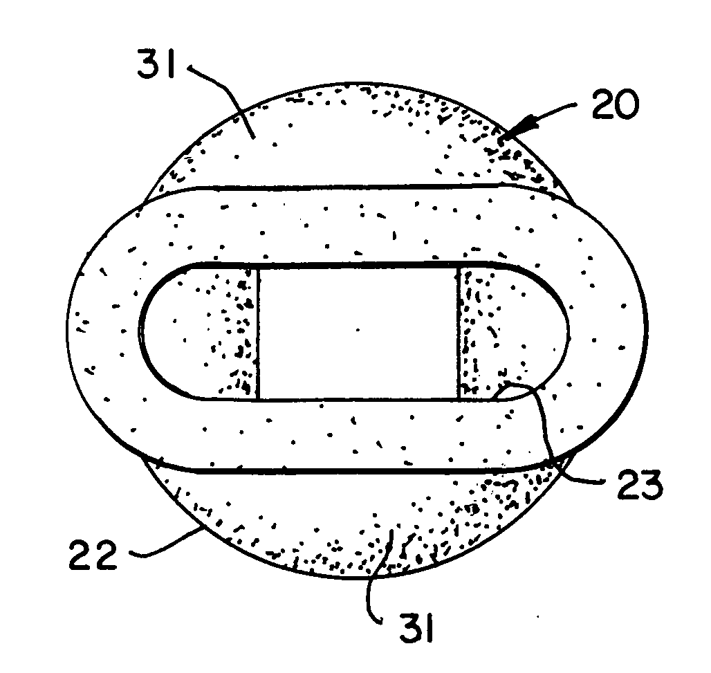
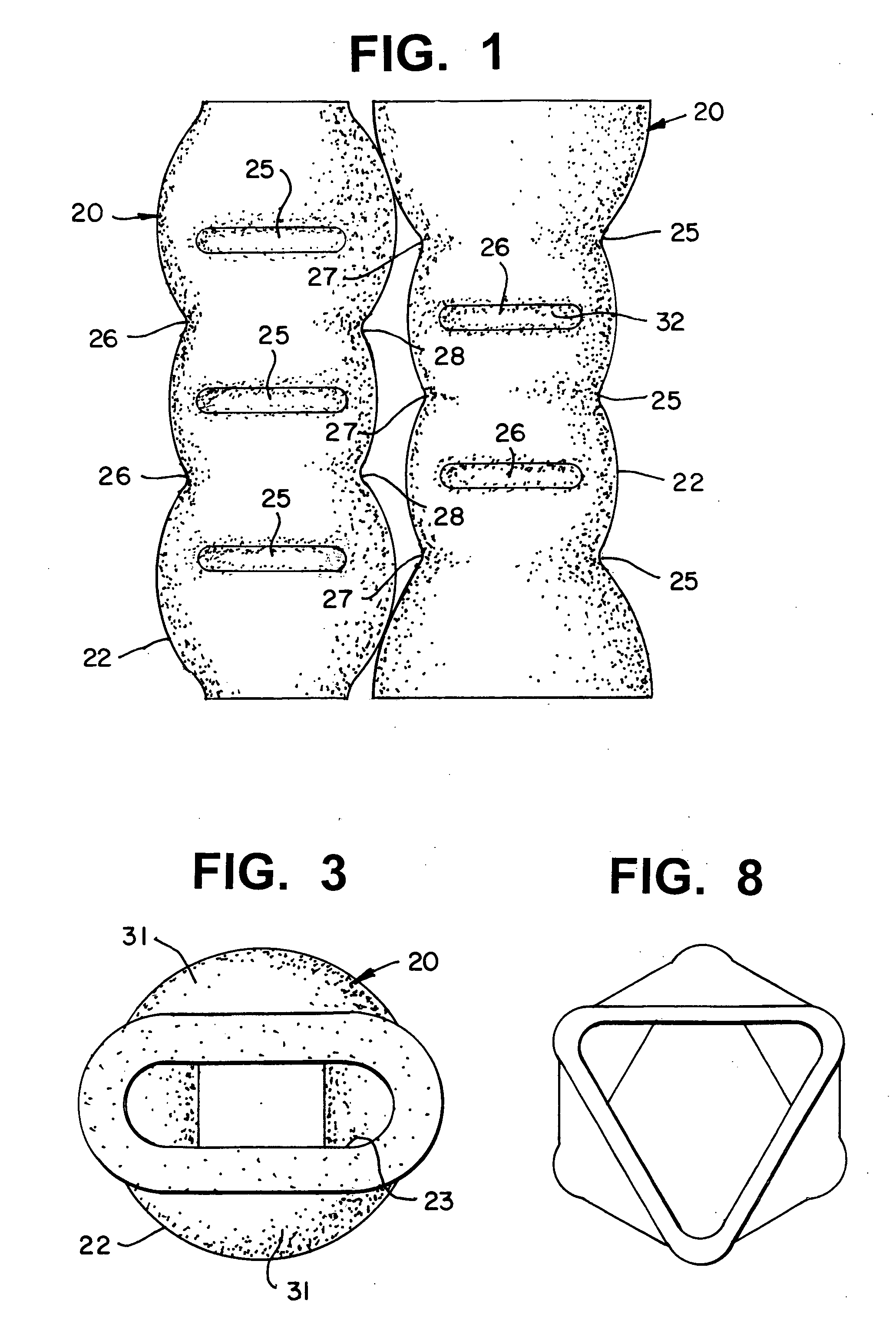
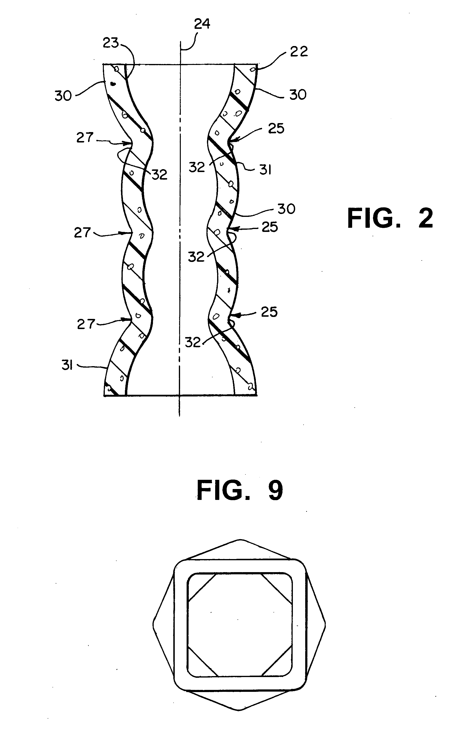
[0056] By referring to FIGS. 1-17, along with the following detailed discussion, the preferred construction of alternate embodiments of the cushioning / supporting element of the present invention can best be understood, along with the use of the elements of the present invention in the bedding and furniture industry. In addition, alternate methods for producing the load bearing, cushioning / supporting elements of the present invention are fully disclosed. However, although this disclosure details the preferred embodiments of the present invention and the methods of production therefor, alternate constructions and methods of formation are capable of being employed without deviating from the scope of the present invention. Consequently, it is to be understood that the following detailed discussion and associated figures are provided for exemplary purposes only and are not intended as a limitation of the present invention.

[0057] In FIGS. 1 and 2, one preferred embodiment of the three-di...


PUM

PropertyMeasurementUnit
densityaaaaaaaaaa
densityaaaaaaaaaa
thicknessaaaaaaaaaa

Abstract

By providing an elongated profile which incorporates a plurality of indentations formed therein, a load bearing / cushioning / supporting element is realized. By employing this construction, the element accommodates large strain under force, and shows good resiliency and repeated recovery. The element can be produced from a continuous extrusion process with immediate manipulation to re-shape the extrusion profile, or secondary thermal forming process which follows the extrusion process, or blow molding process, or injection molding process.

Description

RELATED APPLICATIONS [0001] This application is related to U.S. Provisional Patent Application Ser. No. 60 / 691,917, filed Jun. 17, 2005 entitled FOAM, LOAD BEARING OR CUSHIONING ELEMENTS AND METHOD OF MANUFACTURE. FIELD OF THE INVENTION [0002] The present invention relates to load bearing, supporting, and / or cushioning elements and, more particularly, to load bearing, supporting and / or cushioning elements for use in supporting and / or resisting loads in various products. BACKGROUND OF THE INVENTION [0003] The creation of effective, easily produced, and competitively priced load bearing, supporting, and / or cushioning elements has long been sought in many different and diverse areas. In this regard, the need for load bearing, supporting, and / or cushioning elements is a requirement in many industries for use in many end products, as well as in transportation, product safety, and product protection. As a result, substantial effort has been expended in developing and improving existing pr...

Claims


Application Information

Patent Timeline
Patent Type & Authority Applications(United States)
IPC IPC(8): F16F1/36
CPCA47C27/065A47C27/144A47C27/20Y10S5/953F16F1/376F16F2230/02F16F1/373
Inventor CAO, BANGSHULAUER, EDUARDOALLMAN, MICHAEL W.
Owner NOMACO
Learn More